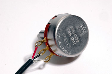
Secure a two conductor shielded cable to the output potentiometer. Attach the shield to the CCW lug.
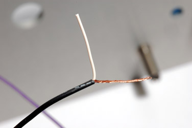
Prepare the last wire from the ratio board connector as follows. Strip a fairly long piece of the outer insulation.
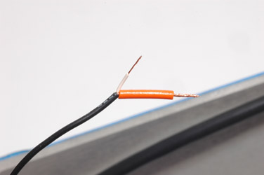
Slip a piece of insulation over the long shield. Cut the inner conductor somewhat shorter and strip the end of it.
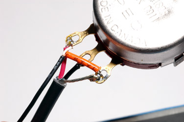
Now attach this assembly to the output pot. Tie the two shields together and solder them in place. Secure the inner conductor of the shielded ratio board wire to the CW lug of the output pot. Solder all connections.
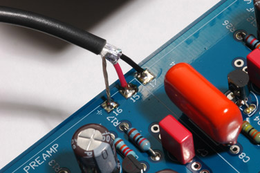
Attach the output pot to the front panel. Solder the other side of the output pot two conductor shielded cable to the main PCB. The shield goes to pad 16. The CW lug goes to pad 15 while the wiper (center) lug goes to pad 17.
Note that the pads are not in numerical order!
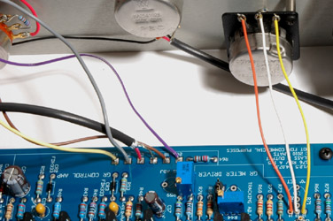
If you decide to use a front panel zero adjustment control rather than a trimmer potentiometer soldered to the main PCB use the following instructions:
Solder the "0" set potentiometer as shown. CW lug to pad 12, center lug to pad 13 and CCW lug to pad 14. On the Rev F USA boards, use the pads for R55 - the "ZERO ADJ" trimmer footprint.
)
)
)
)
)
)