Start by wiring the input (female) XLR as shown.
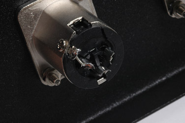
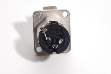 Use a short, thick piece of bare wire to attach pin one of the XLR to chassis ground. By attaching pin one to the chassis, the chassis becomes and extension of your input source's shield.
Most modern XLR connectors have a chassis ground lug. If yours does not, you could attach your own lug to the chassis as close to pin one as possible and connect them with a short, thick piece of wire.
When attaching the XLR input connector to the chassis itself, ensure that the body of the XLR makes electrical contact with the chassis. You may need to scrape some paint off the chassis or use star lock washers to bite into the metal. Test continuity between the chassis and the body of the XLR with your multimeter. If you are front mounting the XLRs - that is, you are placing the main body of the XLR connector through the mounting hole - you will have to leave it mounted before soldering the wires. If you are rear mounting where the main body is behind the panel and does not pass through the hole you may leave it off the body for now.
If the connection between pin one and chassis ground causes problems due to ground loops when connected other equipment, it is possible to lift the ground at this point (pin one disconnected from the chassis). But please connect pin one to the chassis first and change it only if problems are uncovered later.
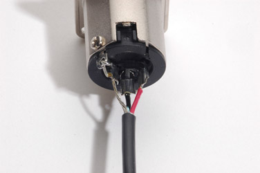
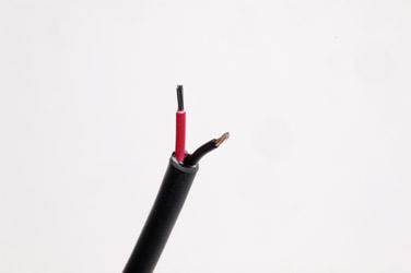
Next, strip and solder a 30cm length of two conductor shielded cable to the XLR as shown - shield to pin one, red wire to pin two and black wire to pin three. I've used Belden 8451 in the example but you can use any two conductor shielded cable here.
You could use balanced microphone cable here but the bulk and stiffness quickly becomes troublesome and the durability of good microphone cable will go to waste in an enclosed environment where the wire will go undisturbed for years.
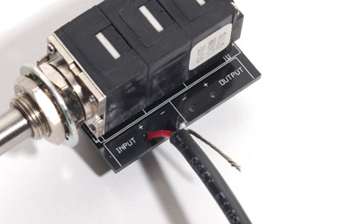
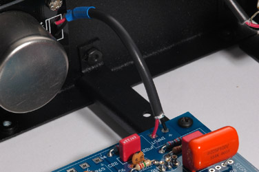
Connect the other end of this cable from the XLR to the input of the T-Attenuator printed circuit board as shown - red wire to the input positive and black wire to the input negative. The shield stays disconnected for the moment.
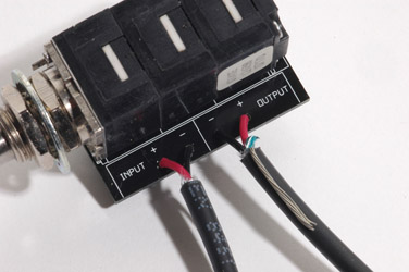
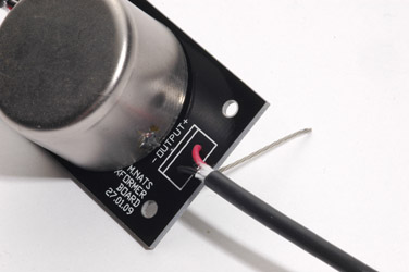
Take a second piece of shielded two conductor around 15cm long, strip it and solder it to the output of the T-Attenuator PCB as shown - note that the positive and negative pads on the board are reversed from the input!
This should leave you with two shields disconnected and both red and black wires of each length of cable connected to the T-Attenuator board.
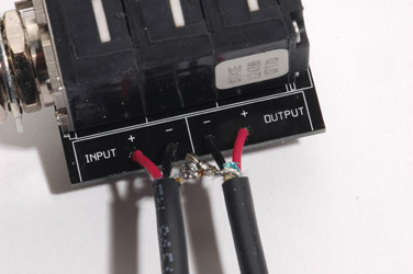
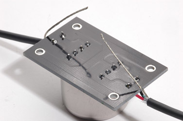
Now tie the two shields together and solder. Make sure that there is no excess of bare wire exposed on the top side of the PCB from the two insulated pairs soldered to the board. There is no need to insulate the shield connection as long as it is kept well away from the other wires.
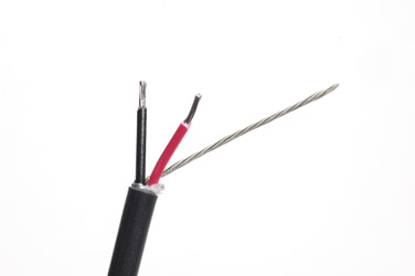
Strip the other end of the cable coming from the output of the T-Attenuator board as shown.
Note that the shield is left long while the inner two conductors are shorter. Later, we will be connecting this shield with yet another shield under the Input Transformer printed circuit board. The shield must be left long to cover the distance required.
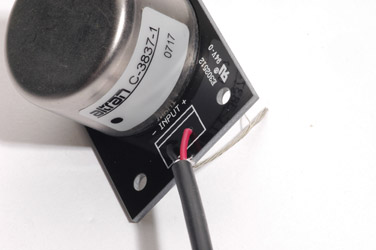
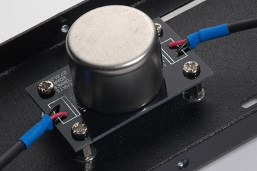
Solder the wires to the Input Transformer PCB as shown - red wire to the input positive and black wire to the input negative. The shield is left unconnected for now.
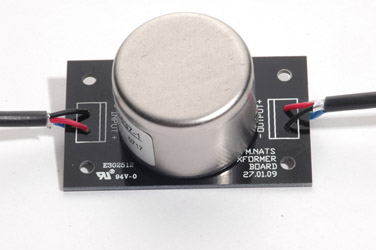
Note the orientation of the input transformer - the black dot on the label corresponds to pin one of the transformer. If your transformer isn't mounted this way, fix it before moving forward!
Take a third piece of two conductor shielded cable 12cm long and strip it as shown previously with the two inner conductor pairs cut short and the shield left long. Solder it to the input tranformer board's output pads as shown - red on the positive pad and black to the negative pad.
Your input transformer board should look like this from the solder side.
Take a moment now to note that Pad 6 of the input transformer board connects to each of the mounting holes through thick tracks. These conductors connect Pin 6 of the input transformer, which is connected to the transformer can, to chassis ground. While it is possible to connect the shields to these points on the Input Transformer PCB, it is better practice to connect just the shields together alone rather than through the PCB.
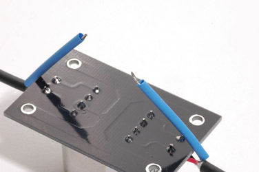
Add a piece of shrink tubing to each side of the shield. Keep the length sufficient to cover the shields but leave enough room to allow the two shields to be soldered together. Keep in mind that the shrink tubing length will remain about the same - it's primarily the diameter that changes when the tubing is heated.
Go ahead and shrink the two pieces of tubing so that they end up looking like two lengths of normal insulated stranded hookup wire.
Tin the ends of the wire in preparation for soldering them together. Do this now or it will likely affect the next piece of heat shrink tubing you'll add to this part of the assembly.
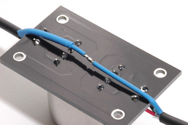
Put another piece of heatshrink over one of the shield ends. You'll want to position this last piece of heatshrink over the joint so ensure that it is long enough to cover the soldered area you are about to connect.
Now solder the two shields together. Do this quickly or you will fuse the third piece of heatshrink to the piece below and it will be difficult to move.
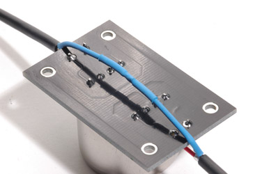
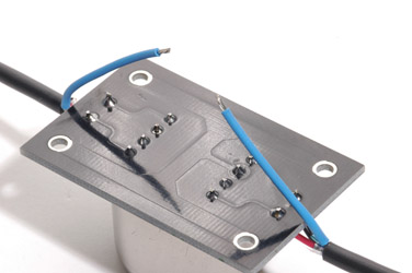
Slide the last piece of heatshrink over the joint and shrink it. When the input transformer shield wiring is complete it should look like the picture. Note that while the solder joint would not be able to short to any of the pins without the last piece of heatshrink, it prevents the joint from contact with the chassis where it may - however unlikely it might seem - cause problems.
When the input transformer wiring is finished it should look like the images above.
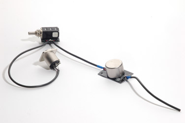
The completed input circuit assembly should look something like this so far. I've put a couple extra pieces of heat shrink over the input transformer cables just for appearance sake.
You can go crazy with the heat shrink and put it over your soldered joints on the XLR as well but I do not recommend that you do this. The reason is that the wire can break inside the heat shrink and you will spend hours trying to figure out what is wrong. Better to keep solder joints exposed where possible so their integrity can be visually checked easily.
Strip the end of the remaining two conductor shielded cable coming from the output of the Input Transformer board. Remove the shield foil or braid and/or wire completely so that the only remaining wires are the two internal conductors.
The shield connects only at the XLR at one end. What you have now is a shielded input assembly that will shunt any interference to the chassis ground away from audio ground. This will keep the audio path free of any internally generated noise that might develop inside the cabinet.
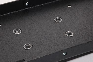
It's important that the Input Transformer PCB makes electrical contact with the cabinet. To facilitate this, you may need to scrape away some of the power coating from around the input transformer board mounting holes. Alternatively you might use some star (lock) washers on the screws holding the standoffs to bite into the metal.
Screw the standoffs to the side case and screw the Input Transformer PCB to the standoffs. Orient the "OUTPUT" side of the board toward the rear of the cabinet. This will place the transformer output pads close to the correponding input pads of the main PCB as shown in the next image.
Test for continuity between the transformer's metal case and the cabinet itself. If there is no continuity, fix the problem before proceeding.
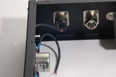
If you are rear mounting the input XLR connector, mount it now to the rear panel. Test for continuity between the body of the XLR and the cabinet. This is vitally important to ensure proper grounding of the input assembly.
Finally, connect the two remaining wires to the main board - black to ground and red to the input positive pad (simply marked "INPUT" on my A/D/F boards). Congratulations - you have completed the wiring of the input circuit.
)
)
)
)
)
)
)
)
)
)
)
)
)
)
)
)
)
)
)
)
)