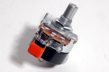
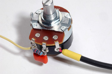
Mechanically secure the correct value resistor and capacitor in parallel to the attack potentiometer as shown. Here we are using the Alpha RV24A02F-10-15S1-BF4 potentiometer with the SPDT switch.
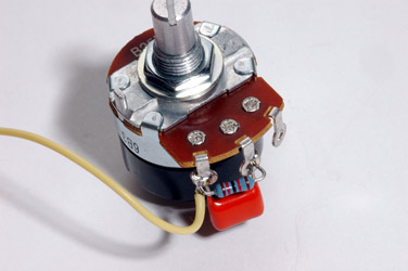
Next, attach a yellow wire around 14cm long to the counter-clockwise lug.
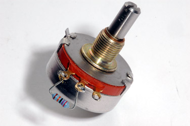
Secure the correct value resistor to the release potentiometer.
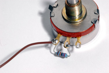
Attach a brown wire about 15cm long to the CCW lug.
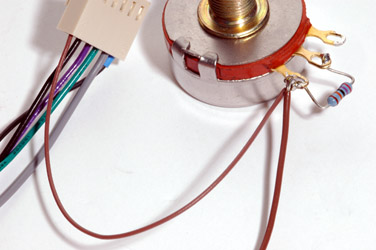
Now, attach the brown wire from the ratio plug assembly we made in the earlier step. Solder all wires to the pot.
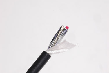
Prepare one end of a 33cm long piece of shielded wire as shown. First, strip the outer insulation.
Remove one of the inner conductors if using a two conductor shielded cable and remove the foil shield, if any.
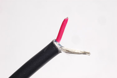
Next, remove the ground wire.
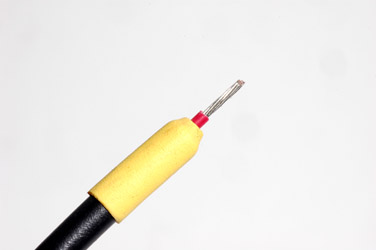
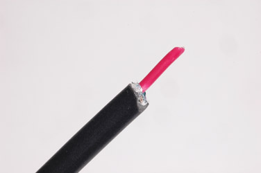
Add a piece of heat shrink so that the shield cannot possibly touch any part of the circuit from this end.
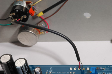
Secure this prepared shielded wire to the clockwise lug of the attack pot as shown.
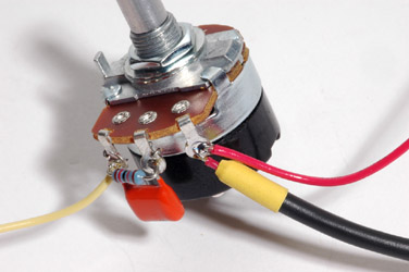
Add a piece of red wire to this same lug and solder both wires in place.
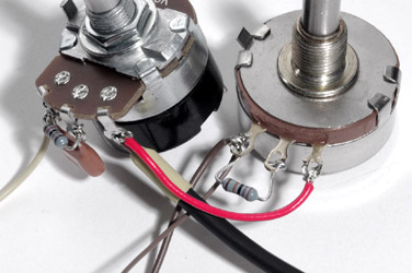
Solder the other end of the red wire to the CW lug of the release potentiometer as shown.
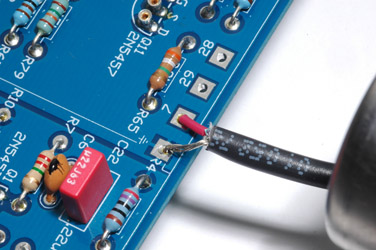
Attach the other end of the shielded wire coming from the attack pot CW lug to the main PCB - shield to ground and the inner conductor to pad 7.
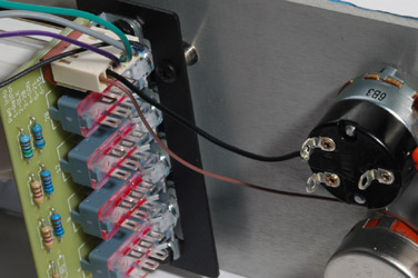 Mount both the attack and release potentiometers to their respective mounting holes on the front panel. Connect the black wire from the ratio plug assembly pin 2 to lug "B" of the SPDT switch on the back of the Alpha attack pot.
This is the "normally open" (NO) lug of the switch, that is, when the pot is turned in any but the most counter-clockwise position this lug is open circuit with respect to the common lug.
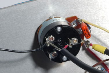
Attach the shield of a single conductor shielded cable to lug "B" of the attack pot and solder the shield and black wire in place. Attach the inner conductor of the shielded cable to lug "C" (common) of the SPDT switch.
Next, run the green wire from the ratio plug assembly pin 4 to lug "A" of the SPDT switch. Solder the wire in place.
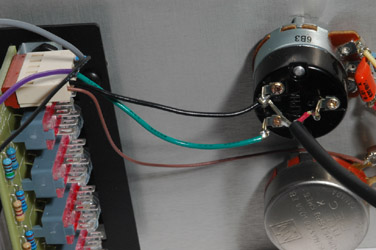
Solder the other end of the shield of the shielded cable to the ground pad next to pad 22 on the main PCB. Solder the inner conductor of the shielded cable to pad 22 on the main PCB.
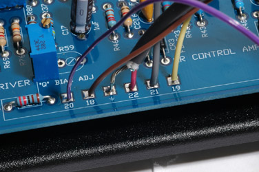
Solder the violet wire from the ratio board connector to pad 20. Solder the brown wire from the release pot to pad 18. Solder the grey wire from the ratio board plug to pad 21. Solder the yellow wire from the attack pot to pad 19.
)
)
)
)
)
)
)
)
)
)
)
)
)
)
)
)
)
)