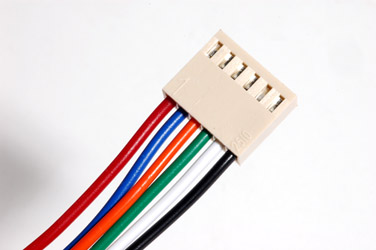
Prepare the meter board Molex socket as you had with the ratio board socket.
| Pin Number |
Wire Color |
Wire Length |
| 1 |
Red |
LONG |
| 2 |
Blue |
LONG |
| 3 |
Orange |
40cm |
| 4 |
Green |
40cm |
| 5 |
White |
20cm |
| 6 |
Black |
20cm |
At least two builders have recently pointed out on the Group DIY forum that, as shown in the table above, the red wire would go to the pad marked "X" on the Hairball meter board while the blue wire would go to the pad marked "Y". This appears to be the reverse of how it is wired on the schematic.
While this is true, if they had bothered to look at the tracks on the Hairball PCB they would have seen that the pad marked "X" goes to the two resistors while the one marked "Y" goes to the switch. In other words, the silkscreen legends on the boards as supplied (January 2012) are reversed in relation to the original schematic. Either way, the polarity of X and Y don't make any difference here. But the proposed wiring in the table above agrees with the schematic and is therefore correct.
Make sure these red and blue VU meter wires are long enough to route them well clear of the input circuit on the main PCB or you will have problems with feedback at high gains.
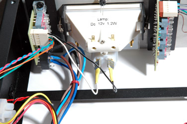
Attach the black and white wires from pins 5 and 6 from the meter board connector to the VU meter as shown. The polarity is not important.
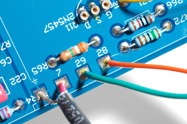
Solder the green and orange wires from pins 3 and 4 of the meter board connector to pads 28 and 29 of the main PCB. Pin 3 of the meter board connector goes to pad 28 of the main board and pin 4 of the meter board connector goes to pad 29 of the main PCB.
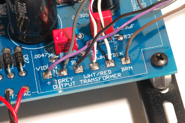
Attach the wires from the output transformer to the main board as marked. It is virtually impossible to screw up this step if you simply look at the markings on the board or refer to the correct overlay available on the respective revision's page on this site.
Don't refer to outdated or incorrect drawings when wiring this or any other step. Just use the proper verified colors printed directly on the board.
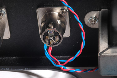
Twist together the blue and red wires from the meter board connector and the transformer secondary from the output transformer for the Rev A or D. For the Rev F, refer to the schematic for the output transformer secondary wiring. Solder to the male output XLR as shown - a short, thick wire connects pin 1 to the chassis; the blue wires go to pin 2 of the XLR; the red wires go to pin 3 of the XLR. If you reverse these wires the polarity of the signal will be reversed in respect to the input. NOTE: If you are using an original or Hairball 5002 reproduction output transformer, you must also connect, solder and heatshrink the yellow and orange output wires to each other. This will place the output windings in series per the schematic. On the Cinemag or Purple output transformer reproduction this is already done internally inside the transformer itself.
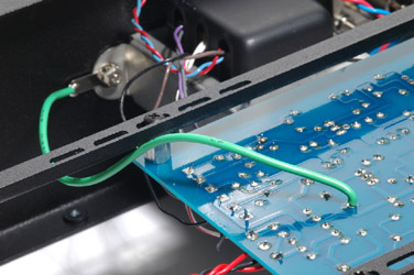
Solder a wire from the board ground nearest the large capacitor in the power supply. If your board does not have a pad here simply solder the wire to the negative pad of the large power supply capacitor C25.
Solder the other end of this wire to a lug and attach it with star washers to a convenient chassis ground point (not the ground for the IEC).
)
)
)
)
)
)