The mnats revision D printed circuit board for the 1176 DIY project will allow you to build a near-exact replica of the 1176LN Revision C/D/E compressor with the correct external components, but also allows room for experimentation in the output and, particularly, the input circuit. There are subtle differences between these revisions; I've named this one Revision D because this revision incorporated the low noise circuitry on the printed circuit board and this is what I have done as well. The original units used a Class A line amplifier with a special output transformer that had an additional feedback winding and a winding to compensate for the DC offset of the output stage. This output transformer has been duplicated by Cinemag and Purple Audio. The output transformer is available direct from Cinemag.
The boards are 3.7" x 6.7" (94mm x 170.2mm) so two of them will easily fit in the average 2U rack case.
Even if you are able to obtain the exact input and output transformer, there will still be a few things that are altered from the vintage units, however. Some differences between the original Revision D and the mnats Revision D are:
The power supply is taken from a later revision. It uses a three-terminal regulator for the +30V 50mA rail rather than a hard-to-get power zener. The negative supply is unchanged.
A trimmer potentiometer has been used in place of the selected, fixed resistor (R44) in the original. This allows quick, easy adjustment of the Gain Reduction Meter Driver Amplifier without resorting to hand-selected resistor values and by eliminating the need for soldering-in parts after the unit is completed. The trimmer serves the same purpose as the Tracking Adj. (R54) on later versions that used an IC for the driver amplifier circuit.
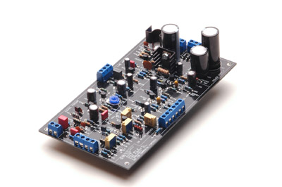
Professionally fabricated boards have the component designations and values printed on the board. Component designations are clearly visible even after the boards have been stuffed with components to ease troubleshooting and future repair or modification.
The physical layout of the board closely resembles the arrangement of the schematic diagram and each circuit block is clearly outlined and labeled. This is to promote a clearer conceptual understanding of the circuit to allow each circuit block to be analyzed in isolation, if required, and to make it simpler to trace the audio and control signal paths of the circuit.
Stuffing The Boards
I would suggest that you test each component before stuffing it in the board. It only takes a few seconds to verify a resistor value and the time you spend beforehand will - one day - save you hours of finding that faulty component after all is said and done and you're faced with a non-working piece of equipment. Even if your eyes are very good and you know the resistor codes backwards and forwards you can usually count on a bad component if you don't check before inserting it into the board.
All of the original components needed for the printed circuit boards are currently available. The bipolar transistors are manufactured by Central Semiconductor Corp. and the FETs are available from Fairchild, On Semi and others. All of the parts should be available from Mouser. If substitutions are required or desired please note the pinouts of replacements carefully. These original "trailing edge" bipolar transistors have a different pin assignment than newer devices. Similarly, "European" BC devices have different pinouts as well.
As indicated on the original schematic, some details regarding the transistors should be noted. Select Q12 and Q13, matching hFE within 10% (the absolute value is not critical). This will allow proper calibration of the meter driver circuit and correct operation once calibrated.
Q7 through Q10 must be selected for an hFE of 250 or above. Additional transistor footprints have also been provided to allow for the substitution of alternate devices for Q7-Q10 in the Gain Reduction Control Amplifier such as the 2N5088 used in the Purple Audio MC76.
Matching Q1 and Q11 may ensure accurate tracking of the gain reduction metering circuit that reflect the actual behavior of the audio gain reduction. However, keep in mind that the meter circuit provides a visual indication of the audio signal, so accurate matching of these parts might not be essential. You may wish to select FETs for a particular threshold range.
For the Version 2 PCBs currently being supplied, there are additional footprints for Q5, Q12, and Q13 so 2N5088s can be used in these positions too. This is simply as an added convenience; if you cannot obtain the original transistors or if you happen to have 2N5088 transistors lying around you can use them here. The higher beta isn't required in these positions but won't cause a problem either. Use the alternate base pad between the collector and emitter pads that form a triangle. The inline pads are for the 2N3707/8 devices. Refer to the manufacturer's pinout if you are unsure.
Capacitor footprints were selected to match the dielectric type suggested by the schematic and are sometimes based on knowledge of the original circuit. Non-polar capacitors of a typical range covered by modern plastic-cased metalized polyester types have 0.2" pitch as does the range covered by ceramic types, while electrolytic footprints were chosen for pitch relative to capacitance value and voltage. Alternate dielectric choices are left up to the builder, and additional footprints are provided in locations where parts are typically substituted - in the audio path.
It is worth keeping in mind that resistor tolerances in the original unit were 5% while a tolerance of 1% is typical today even with off-the-shelf parts. Try not to become too obsessed with using the exact values indicated except where 1% values are specified. The only crucial part of the circuit is the second block of the Gain Reduction Control Amplifier, where the signal is inverted with a gain of exactly 1 (with the suggested components, assuming absolute precision of values).
These values ensure that both the positive and negative swing of the input signal is treated identically. The magnitude of a given signal is accurately converted into an exact DC control voltage regardless of the polarity. Imprecision in this circuit might result in different levels of gain reduction if the same asymmetrical signal is inverted in polarity. It is clear from the schematics that the designers saw it fit to select components in the early versions and to make use of precision resistors in this part of the circuit when they became available.
If these exact values are unavailable to the builder, some suggested replacements using typical values are suggested below. Use each of the specified values in sets, without replacing any one value for another. This will ensure the greatest accuracy when using common values.
ID:
R42
R43
R47
R48
Set 1:
180k
36k
43k
7.3k
Set 2:
180k
39k
43k
7.5k
Set 1 will give a gain of 0.98 (1.83% error) and Set 2 gives a gain of 1.02 (2.1% error). Either set should ensure reasonable performance.
Leave R44 - the Tracking Adjust trim pot - off the board until you have calibrated the meter circuit according to the 1176LN manual from the JBL Pro Service site.
With the Version 2 boards a footprint is provided to either wire a link or solder in a three pin header to put the Tracking Adjust trimmer in or out of circuit. The trimmer is normally out of circuit on the Version 2 boards so you will have to link the rounded rectangular pads together once the initial Null Adjust trimming is done, otherwise your gain reduction meter circuit will not operate correctly. The square third pad is provided as a place to put the shorting plug temporarily if you use the header scheme.
Please refer to the manual linked in the paragraph above for a full explanation of the calibration procedure. Alternatively, you can refer to a post by Studio Electronics' guru David Kulka: here for Rev D calibration in a nutshell.
Wiring Details
All external wiring points on the main board terminate at the edges of the board and are placed on 0.2" centers. This makes them ideal for screw terminal blocks, simplifying wiring and allowing alterations to be made without de-soldering and potentially pulling up printed circuit board traces. Edge placement helps keep the wiring neat and tidy by eliminating routing of hookup wires over the center of the board surface.
The AC input pads have been offset from the output transformer connections to provide a clear visual demarcation between them and prevent catastrophic wiring errors from occurring. Output transformer designations are for the Cinemag replacement transformer. Colors are marked on the board and on the PDF overlay screen layer page.
Generally, wiring the Revision D is the same as wiring a rotary version of the G1176. One subtle difference is that the GR (Gain Reduction) meter setting doesn't ground one terminal of the VU meter in the discrete version as it does in the IC circuit and special rotary control PCBs have been designed with this in mind. Please refer to the original schematic if you have any doubt about the wiring.
I've had a chance to try Ed's transformer with my Rev D board and to compare it to the Cinemag CM-96731.
The first image shows the Cinemag CM-96731 with a 1kHz square wave terminated to a 10k load - fairly typical of modern line input impedances. Notice there is a little ringing. Click on any of the images for a larger version.
The next image is the same 1kHz square wave terminated into a 10k load but using the EA-5002. This transformer exhibits a more naturally damped response than the Cinemag and into this highish load there is no ringing. The output was a couple of tenths of a volt lower (as measured on an external AC Voltmeter) - nothing to worry about at all.
The response of the Cinemag shouldn't be a big surprise and certainly doesn't mean that it is somehow intrinsically worse or better than the EA-5002. Back in the day when the 1176 was designed most equipment had a 600 ohm input impedance - much like the input of the 1176 itself. The next picture above shows the Cinemag terminated into a 619 ohm resistor. Notice that the ringing is completely gone now.
If you will be feeding the output of your Rev D into a modern line input with high impedance you may want to put a load resistor across the output. On the other hand, you may think it sounds better without one. Check out the last comments in this post from W O'B.
I also did a sweep to find the -3dB upper limit of the two transformers. I fed a sine wave into the input until I had a +4dBm output at 1kHz. The Cinemag was -3dB at 58.1kHz while the EA-5002 was -3dB at 60.2kHz.
So either transformer will make a fine match for the circuit. Personally, I like the vintage look of Ed's model and I would guess that the lower price compared to the Cinemag will be attractive for a lot of builders especially considering that there are no performance compromises.
The EA-5002 will also fit right into a 1U rack case without any modifications. The color code is the same as the Cinemag except for the output secondaries. The EA-5002 has two secondary output windings - four wires like the original - that are ordinarily connected in series. The Cinemag is connected internally, so it has only two wires at the output. Refer to the original schematics in the 1176 manual linked in the sidebar if you have any questions. The colors match the original diagram exactly so again the original schematic is your best guide for wiring. Currently, the EA-5002 is available from Hairball Audio.
The first video will actually be the second in the planned series (the first will be an introduction to the tools and requirements to begin the calibration procedure). This video describes the "Q" Bias Adjustment. Though the procedure is essentially the same for all revisions of the 1176, this video is specific to the Rev C/D/E in that it names the trim pot by those revision's designation for the pot (R59).
Please note that there is an error in the video. At 1:54 the video says to turn the trimmer so the wiper is closest to ground. In fact, you want to turn the trimmer so that the wiper is in the opposite position or furthest from ground. The direction of rotation will vary depending on the type of trimmer used and the revision on which you are working. Your initial setting should allow the maximum signal to pass through before you perform the calibration.
Next is Step 2: Calibrating the Discrete Meter Circuit.
Please note that the video below describes the second step of the calibration process. It must be performed after the "Q" Bias Adjust described in the video above, otherwise the adjustment is meaningless. Sequentially, this adjustment comes before any of the other calibration steps of the gain reduction meter circuit.
This step applies only to the DIY Revision A and D boards with the discrete transistor meter circuit, not to the G1176 or similar Revision F or later boards with the IC in the meter circuit. The Rev F or later circuits do not require this calibration at all. Note that on the Rev A you put your meter on the null test points between the two collectors. There is no resistor at this location on the Rev A as there is on the Rev D.
The next step applies to all versions of the 1176 limiter.
The distortion adjustment video will be posted here as soon as it is completed.
Revision D Version 2 10.03.08 errata:
R15 Value on overlay should be 6.8k rather than 7.5k
R64 Value on overlay should be 1.5k rather than 2.2k
Revision D Version 2.2 26.01.09:
R12 Value should be 1.8k rather than 920
Revision D Version 2.2 25.02.13 (currently being supplied):
)
)
)
)