Please note that the following instructions are for a single channel of the rotary switch version only (as opposed to the pushbutton version) and apply to either my or Jakob's original rotary switch PCB layouts. While there are some similarities between wiring the pushbutton version and the rotary, there are many differences too.
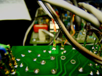
In my example photographs for the rotary version, I've used "matrix pins" and plugs to make the electrical connections between the boards and other components. One benefit of matrix pins is they make it easy to change your wiring if you make a mistake.
I've attached the pins to the back (copper) side of the rotary switch boards. I did this because it makes it much easier to plug in the corresponding connectors rather than trying to squeeze your fingers in between the board and the front panel. If you are planning to solder wires directly to the boards it is always best to pass the wire from the "top" (silkscreen) side of the board through the holes rather than soldering them directly onto the copper side. This is because the holes provide a little mechanical support to the wire which is important for strong, reliable connections.
You'll see as you go along that wiring the 1176 clone is basically like painting by numbers - all the hard work is already done for you. You just have to match the numbers on the main board with the ratio and meter boards, in most cases.
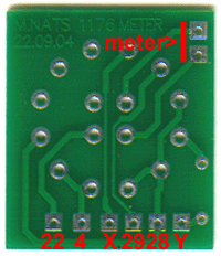
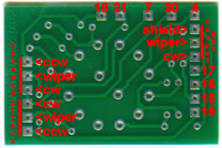 Because all of my shots of the ratio and meter rotary switch boards are shown with the printed circuit boards upside-down, I've made up some scans to give an overview of where the connections are made. Of course, if you have my boards in hand, you can just flip them over to see the silkscreen designations but these pictures should help you out if you are doing a home-etch or are using other boards that don't have all the designations. (Note: the ratio board, like most of the images on this page, enlarges if you click on it but the meter board below it is shown full-size).
 I've included potentiometer assignments too that aren't on the silkscreen layer of the boards: ccw=counter-clockwise - the contact where the wiper comes to rest if the shaft is turned all the way to the left when the pot is viewed from the front; wiper=the middle contact; cw=clockwise - the contact where the wiper comes to rest if the shaft is turned all the way to the right. If you have any doubt, turn the shaft all the way to the end stop and measure the resistance from the middle terminal to each of the other lugs. The one that shows the lowest resistance is the one where the wiper is closest to. It should read very close to zero ohms.
Keep referring to these shots while you wire your clone if you need to. I will always refer to the board shown in the photos within the text next to it but I don't always show the entire board, making it difficult sometimes to see exactly where you are. Hopefully these scans will make everything a bit clearer.
 Next up for the rotary specific wiring is the output potentiometer. In the rotary version, the potentiometer is wired to the ratio switch board, which in turn is wired to the main board. The reason for this is the rotary ratio switch circuit requires an electrical connection to both the potentiometer and ground. Wiring the pot to the ratio board is one way to accomplish both goals.
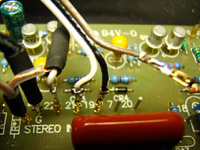
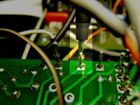
Wire a length of two conductor shielded cable to the points marked 16 15 17 on the main circuit board. Note that the outer shield is connected to terminal 16.
 The opposite end of the cable you just soldered to the pot goes to pads 15, 16 and 17 on the rotary ratio board. Again, if you're not using matrix pins pass the bare wire through the holes on the opposite side of the board before soldering. Note that the shield is connected to pad 16 which here is in the middle of 15 and 17.
Note that R23 (47k) connects to this ground connection via the trace running from pad 16. This creates the "bottom" of the resistor divider network to feed the GR Control Amp from the Signal Pre-Amp which operates independently of the output gain control (refer to schematic).
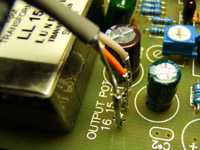
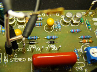
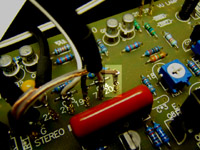
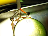 Using two conductor shielded cable, wire the output pot as shown. Use any colors you want, just make sure they correspond to the correct points on the opposite end of the cable...
 Wire the other end of the output pot cable to the three output pot pads on the ratio board which are right next to pads 15, 16 and 17. Note the arrangement carefully - shield on the outside (with the trace running to the other shield wire), wiper terminal in the middle.
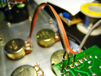
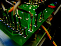
 Here's an overview of the output pot wiring as the cable makes the leap from main board to ratio board and finally to the pot. It really isn't too different from the way I wired my pushbutton version except that in that version I tapped off the potentiometer legs rather than creating extra pads on the ratio boards. The connections need to be made somehow.
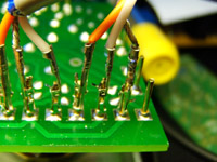
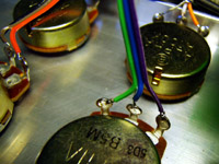
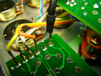
 Next, wire the attack pot. These wires don't need to be shielded so you can just use plain wire or ribbon cable as I did in the example. Just make sure you use different colors so it is easy to tell them apart.
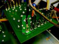
 The attack pot gets connected to the ratio board too. Note carefully where each of the wires goes - wiper in the middle, counter-clockwise leg (the one that the wiper comes to rest on when the pot is viewed from the front and turned to the furthest counter-clockwise point) nearest the edge of the board.
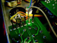
 Wire the release pot (4.7 or 5M) in a similar manner to the attack pot using unshielded wire.
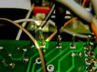
 Attach the other end of the release pot wires to the ratio board. Note that they go in reverse order of the attack pot wires. Look at the violet wire which corresponds to the clockwise rotation of the potentiometer. The wiper goes in the middle again.
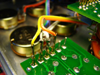
 Take a break from the ratio board for a moment. Find pads 28 and 29 on your main PCB. They are in the upper right quadrant of the board. These pads send a signal to the meter from the gain reduction meter driver on the main PCB. Because the meter does a double duty of reporting output levels and showing gain reduction, these signals are sent first to the meter switch so the function can be selected by the user.
Solder one wire to each of these pads. They do not need to be shielded. You can use ribbon cable as I did or just twist a pair of stranded wire together.
 Run the other end of these wires to the meter rotary switch board. Naturally, you'll want to connect them to pads 28 and 29 on the rotary meter board, and ensure that the ground wire (28) goes to pad 28 and the signal wire (29) goes to pad 29.
The boards I provide are fully silkscreened with the pad numbers; I'm unsure if the boards others provide also have these markings but it would appear from the .pdf file on Jakob's site that the numbers don't quite make it onto the board. Refer to Jakob's .pdf file if you are unsure about the pad designations or have a look at my modified layouts accessible from my main 1176 page (link in left sidebar).
 Now grab the output signal from pads x and y. These pads are located near the output transformer.
The signal from these pads will show the output level of the compressor and will go first to the switch before going to the meter itself.
Again, shielded wire isn't necessary for this application - some ribbon cable or a twisted pair of stranded wire will work fine.
 Run these wires to pads x and y on the meter board. The polarity is actually unimportant so if you happen to switch x and y around you'll never notice it, operationally. But don't make it a habit to neglect this sort of detail as eventually it will turn around and bite you...
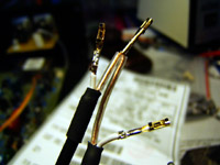 Prepare two lengths of single conductor shielded cable as shown. The idea is to minimise the length of conductor left unshielded, so you'll have to strip back quite a length of the outer insulation, twist (and possibly unbraid) the outer shielding layer, then cut the inner conductor to length.
Put a little shrink tubing over the shield wires and some larger shrink tubing over the gap where the outer insulation was stripped back. The two shield wires are different lengths for a reason - one of the cables is going to connect to pad 22 on the main board and the other is eventually going to connect to pad 7.
Twist the ends of the shields together. These will connect to the ground pad provided on my boards. If you are using Jakob's boards you will have to find a ground point to attach them to.
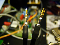 The opposite end of the shielded wires will get prepared like this: The outer insulation is stripped back and the inner shield is cut at the same place to expose only the inner wire. Strip back the inner conductor making sure you don't strip too much and risk shorting to the partially exposed shield.
Put a length of shrink tubing over the exposed shield leaving only the inner wire, or in this case the matrix socket, sticking out.
Only the inner wire is going to be connected at the other end.
 Take the two tied-together shield wires and solder them to the "G" pad on the main board (on the far left). This is the hole that is not in line with the others. Connect the shorter end of shielded cable to pad 22.
You'll notice another cable is connected to pin *1 between the ground pad and pad 22. This is the alternate input pot wire that you use only if you are using an optional input transformer.
Leave the other cable unconnected for a while. There are lots of pads in between and it is easier to access them if you don't have the other wire hooked up and potentially blocking your view.
 Connect the cable that goes to pad 22 of the main board to pad 22 of the meter switch board. Remember that only the inner conductor gets hooked up on this side of the cable. Don't allow the shield to contact any part of the circuit on this side.
Point 22 of the circuit goes to the Gain Reduction Control Amplifier. In Jakob's implementation, the signal that feeds the GR Control Amp goes to the meter switch board first. This is because the meter switch incorporates the Gain Reduction Off function which, on the original, was part of the attack control.
 The signal that feeds the meter switch comes from the resistor divider we looked at earlier, which is part of the ratio circuit. Connect a wire to pad 4 on the meter board. Note that the designation "4" doesn't show up anywhere on the 1176 schematic, it's a marker unique to the clone.
When I wired this particular unit, I used ordinary stranded wire for this point. Looking at the schematic, the point between the ratio switches and the Gain Reduction Off switch is also shown unshielded. But it may be beneficial to use shielded wire here, since that is what is used after the switch.
 Wire the other end to pad 4 on the ratio board, right next to where the output pot wires go.
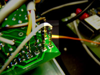
 Solder a wire to pad 21 and another to pad 19. I used ribbon cable again but go ahead and use whatever sort of wire you want.
You'll notice I have another wire waiting for the last pad.
 The wire from pad 19 on the main board goes to pad 19 of the ratio board, right beside the shielded cable that ran from the main board pads 15,16 and 17.
 Solder the wire from pad 21 of the main board to pad 21 of the ratio board.
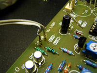
 Now put that other piece of shielded wire you left a while back through to pad 7 on the main board.
 Solder the wire that came from pad 7 of the main board to pad 7 of the ratio board.
 Attach a plain, unshielded wire to pad 20 on the main board.
 Finally, to finish this row of pads, solder the other end of the wire from pad 20 of the main board to pad 20 on the ratio board.
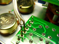
 Solder a plain wire to pad 18 on the main board. Note that there are two holes near the "18" designation. If you use a large trimpot, you may need to use the hole above the "18".
Turn your board over to check which pad you need to use if you aren't sure. Your clone will not work properly without a connection to the wiper (center pin) of the "Q" Bias trimpot here.
 The other end of the wire from pad 18 on the main board goes to pad 18 of the ratio board.
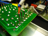
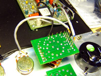
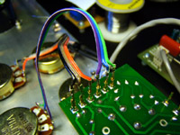
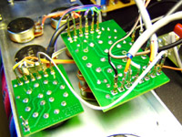 Here's an overview of what you should have so far.
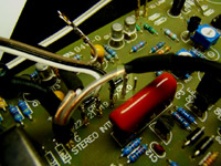
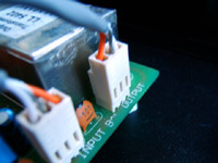
 Now wire the output jack with two-conductor shielded cable. Pay close attention to the markings on the XLR housing - terminal 2 is +, terminal 3 is - and 1 is neutral or shield. Note that the output jack terminals (male XLR) are the mirror image of the input jack terminals (female XLR).
Choose whichever colors you want to use and stick with them. I've used orange to signify +. Of course, the shield is always the outer conductor and attaches to terminal 1.
 The other end of the two-conductor cable attaches to the main board at the output pads. These pads are located right near the output transformer. Please note that if you are using Jakob's rev 7 boards the pad designations are reversed, that is, the pads go - 0 + left to right. My boards go + 0 - left to right, the opposite of the input pads.
The last thing you need to hook up before testing is the meter. By now you should be able to figure it out without a picture. The two pads on the meter board marked "+ METER -" (or M- and M+ on Jakob's boards) go to the two terminals on the VU meter. I don't know why they are marked + and - because a true VU meter contains an internal full wave rectifier so either polarity will give a "positive", right swinging reading. You can use ordinary wire to hook up the meter.
Now calibrate your limiter using the information provided in the manual or do a search at The Lab for more hints. Eventually I will add a calibration page to this site.
Happy compressing!
)
)
)
)
)
)
)
)
)
)
)
)
)
)
)
)
)
)
)
)
)
)
)
)
)
)
)
)
)
)
)
)
)