Created 23 July 2017
Some notes about rotary switch PCBs with R-OPT1 THRESH. Many years ago I created some rotary switch PCBs for my old 1176 clone project that had an additional footprint for a trimmer potentiometer marked R-OPT1 THRESH. This was in response to the perception by some that the limiter kicked in with too low an input signal.
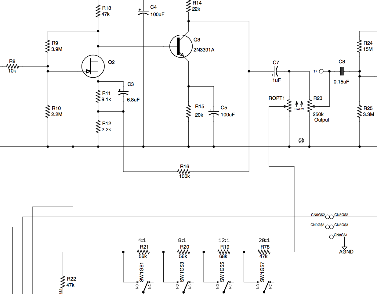
While I can't recall if I had ever tried it myself its operation is quite simple. Ordinarily, the T attenuator INPUT knob controls the input to the Signal Preamp in the 1176. The output of the Signal Preamp goes directly to the voltage divider that makes up the first bank of Ratio switches that in turn feeds the G.R. Control Amp. Since some complained that compression came in too early the simple solution is to reduce the level that feeds the G.R. Control Amp while leaving the single that feed the Output control alone.
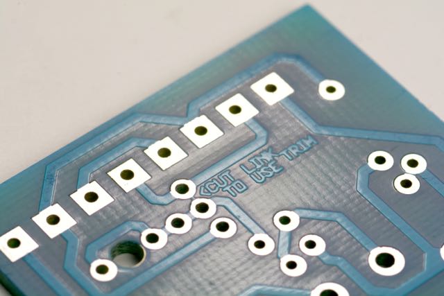
This can be accomplished by adding a parallel potentiometer to the existing Output pot as shown above. With the aforementioned boards, cut the small trace that exists between the two trimmer pads marked with the < symbol. Add a trimmer potentiometer. Experiment with a value of 250k to 1M.
Wiring is identical to any Gyraf-style rotary switch build. Here is my example, though perhaps not the best guide out there. Remember, the schematic is your best guide to wiring.