Have a look at Mark Burnley's transformer connections. Under the "Typical Primary Configurations" we'll be using the 240V Series Connection. Therefore we need to connect one wire to each AC line source, then we need to connect the two primary windings to each other in a specific way.
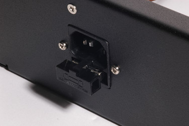
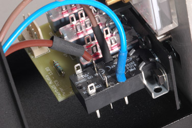 For a 240 Volt mains voltage from the wall, identify the brown wire of the power transformer primary windings. Put a piece of heat shrink over it, thread the wire through the hole in the switch's solder lug and solder it to the terminal closest to the brown wire coming from the IEC power connector as shown in the photograph.
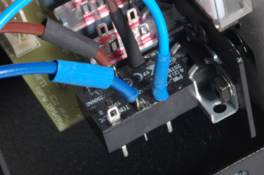 Next, identify the blue wire from the power transformer primary. Put a piece of heat shrink over it, thread it through the switch solder lug nearest the blue wire coming from the IEC power connector and solder the wire to the lug. Note that both the primary wires used so far correspond to the IEC color codes used from the IEC power connector to the previously used switch terminals.
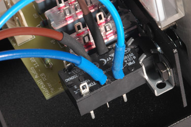 Now slide the shrink tubing over the exposed solder joints and switch solder lugs until all exposed metal is covered by the heat shrink tubing. Shrink the tubing in place.
With a series configuration of the two power transformer primaries one more connection is required or the circuit will not operate at all.
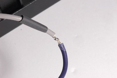
For a 240 Volt dual primary series connection, identify the remaining two primary wires. These wires are grey and violet. Slip a piece of heatshrink over them, then secure and solder them together.
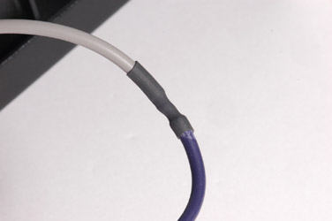
Slide the piece of heatshrink and shrink it over the connection you just made. Make sure it is absolutely secure and that no bare wire whatsoever is exposed.
AC Power Transformer Secondary Wiring
Refer again to Mark Burnley's transformer connections. Under the "Typical Output Configurations" we'll be using the "Split Secondary for +/- Power Supply".
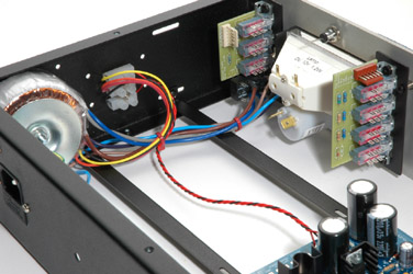
I've used a terminal strip here. A terminal strip makes a tidy way to connect two or more wires together securely and to extend the physical reach of the transformer secondary beyond the usually too short length of the wires attached to the transformer itself.
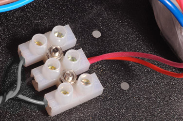
Identify the two wires coming from the power transformer secondary that are closest to each other on the schematic. On the Avel-Lindberg power transformer these are the red and orange wires of the secondary windings. Twist them lightly together and secure them in the middle terminal of the terminal strip.
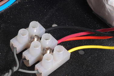 Now take the two remaining yellow and black secondary wires and attach them to either end of the terminal strip. The order of the top and bottom wires is unimportant. Just make absolutely sure you have tied the red and orange wires together as indicated in Mr. Burnley's illustration.
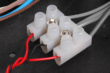
Attach three hookup wires to the other side of the terminal strip as shown. Use two colors as pictured - the black is the center tap while the red are the two AC wires on the outside terminals of the connector.
Later, we'll be adding wires to the connector for the VU meter lamp but for now you can secure the screws after inserting the wires.
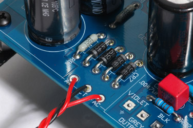
Connect the other end of the wires coming from the terminal strip to the main board as shown.
Check your wiring carefully step-by-step with the instructions above. Make absolutely certain you have wired the AC power correctly. Any error could cause irreparable damage to the power transformer or other components or even yourself!
When you are certain everything is correct, bundle the wires neatly and add a couple of nylon wire ties.
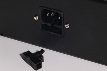
Remove the fuse holder from the IEC power connector.
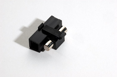
Insert the appropriate 5 x 20 mm fuse in the fuse holder. See this post for the way to select the correct fuse.
This completes the AC wiring of your unit. From here, the power supply built into the main PCB will convert the alternating current into direct current and regulate the voltages to the +30 and -10 Volts required for the rest of the circuit.
)
)
)
)
)
)
)
)
)
)
)
)
)
)
)
)