Secondly, many people had reported the gain of the stock G1176 was inadequate and far below what the original was capable of producing. Jakob suggested a solution and step-by-step instructions were published on the now-defunct Tech Talk DIY Forum by deanp920 (recovered and republished at The Lab). But as it involved reversing the output transformer it required (again) an ugly kludge of cutting circuit board tracks with a Dremel tool and adding pieces of wire.
The last and most important major problem I wanted to overcome was the tendency for the clone to hum. Users reported excessive hum which was traced to ground loops occurring within the PCB itself. A quick scan of the Rev 7 layout revealed a literal loop where the ground trace ran all the way around the perimeter of the board.
This hum problem had been solved with the Gyraf Rev #7 boards by running a heavy ground buss soldered to the ground trace lowering the resistance of the track to a point where the hum was nearly eradicated. Later it was suggested that a wire be run from one side of the board to the other, soldering it where the hum was at its minimum. More recently, a trace cut has been suggested and tried with good results. I thought a more elegant solution to this band-aid approach would be to try grouping the ground points in each circuit block and returning each group separately to a central star point.
All this meant that the PCB would have to be redesigned although not too extensively. The original Gyraf Rev 7 board dimensions are 160mm x 100mm - a format apparently called a "Eurocard". This is a board that evidently is commonly found in pre-sensitised form in the European Union and elsewhere. While I had no such restrictions, usually cutting a board to size and coating it myself with photoresist, I thought I would try sticking to those dimensions anyway to see if it was possible to incorporate all the features into a size and shape many were familiar with. Given the popularity of the Gyraf design, keeping it similar rather than creating an entirely new design seemed sensible.
I secured permission from Jakob to base a new design on his Rev 7 board and set about laying out the parts visually in Protel Autotrax using custom components I had created. I also polled the Forum for additional features others wanted to see and incorporated some of these in the new board.
While I had reservations at first about the Gyraf design - in particular the orientation of parts seemingly only to avoid the need for any wire jumpers - my admiration for Jakob's design only grew as I began "connecting the dots". Though the layout isn't necessarily the most beautiful I've discovered it is truly a masterpiece in its own way. How do all those parts fit on the board? There is very little, if any, wasted space and there are ZERO jumpers.
I don't agree with the assertion that it is a difficult home-etch; it certainly isn't as troublesome as Gyraf's SSL Mixbus Clone layout in that sense. Nor do I believe that it is difficult to stuff the board with parts as others have suggested. Sure you need a little skill but if skill is a problem you should probably think about buying one pre-made anyway. The power supply caps do get a little squeezy but they still fit flush with the board. There doesn't seem to be an easy way around that one.
The new board, dubbed Rev F after my own lettered revisions (having nothing at all to do with the various UREI schematic revisions), incorporates the following features:
- The ability to mount BD135/136 or BD139/140 output transistors without crossing leads and using shrink tubing or mounting them with an unsightly twist. A version for the originally specified BD517/518 pair with all the following modifications also exists.
- Lundahl output transformer is installed 'reversed' to increase gain to the equivalent of the original UREI 1176. OEP is installed natively (its ratio is 1+1:2+2 primary to secondary) for the same result.
- Star grounding scheme isolating the various sections of the circuit and bringing them separately to the star point beneath the output transformer for elimination of hum.
- Options for either OEP or Lundahl input AND output transformers.
- Additional pad for stereo interconnect between two units.
- Three styles of trim pots can be installed on the one board and in any combination.
For no other reason than aesthetics, I also wanted to use push buttons like the original. So I also designed two additional boards using cheap pushbutton switches. They aren't interlocked like the original so you have to push one off before pushing another one.
To hear my nearly finished clone with the modified board playing silence for 5 seconds, then a door closing, click here (151kB mp3 file). This is a recording I made in the Union Street Parking Garage in San Francisco a zillion years ago on my Panasonic SV-255 DAT recorder. I burned it onto a CD with about 5 seconds of silence then the door slam to give an idea about levels and noise.
It was played through an ancient Panasonic SL-S160 CD player through the headphone output into a hastily-made mini-jack to XLR cable, into the 1176 clone with the cover off, the toroid not yet tweaked and the screening can off the output transformer set at the 3/4 mark on input and output with the gain reduction off (passing through all audio stages) out through an equally quickly made XLR-F to mini cable straight into the line in of my Sound Blaster Live! card.
None of the optional bypass or filtering caps were installed (though I have included all pads on my layout). The levels were not changed at any point and the silence (or slight hiss) is the entire audio chain passing the signal up until the door. The resulting recording was then converted to the mp3 format with LAME.
It seems to have been worth the effort. There is very little, if any, audible hum.
Parts
As always when building DIY equipment, the most difficult part is securing the components with which to build the thing in the first place. While the cost of living is generally low in Australia, many specialty or luxury items are priced well beyond what would be considered reasonable elsewhere. Take, for example, the FDH333 diodes. These cost seven US cents from Mouser. That's $0.07. Yet at Farnell's Australian site they cost a whopping $2.55 Australian Dollars each! That's about 25.5 times the price of the same part from Mouser at current exchange rates. RS in Australia sells the BC107 for 2.11 AUD; Mouser's price is 40 cents US.
The OEP A262A2E has been named as a alternative part for the output stage. In April 2004, RS UK listed the OEP transformer for �9.80 or $23.50 Australian dollars. Newark in the US sells them for $19.34 or around $26 AUD. The same item from RS Australia costs $39.10! When you add the screening can and courier shipping (of which you have no alternative) the transformer ends up costing nearly $80 AUD!
With this in mind I hadn't thought to even inquire about the cost of the original Lundahl 5402. But later I did and found out that the Australian distributor actually sells them for a price very much in line with the rest of the world: Control Devices Sydney - $65 + GST, $15 + GST shipping; Canford UK �29.14 = 69.87 AUD; K&K USA $48 USD = $62 AUD.
Control Audio Pty Ltd
Mr. Rick Dowel
Level 6, Westfield Towers
100 William Street
AU-Sydney NSW 2000
Australia

Phone +61 - (0)2 - 9368 7100
Fax   +61 - (0)2 - 9368 7199
Email: 	sales/AT/controldevices/DOT/net
In the end I was satisfied with my OvErPriced transformer though as it apparently has a higher distortion rating than the Lundahl and sounds good and dirty - a positive characteristic for a distinctive compressor like the 1176. One additional note: even though the screening can had been cited as essential in a post on Tech Talk, it isn't necessary at all. There is no difference in the level of hum with or without the screening can.
Semiconductors
The Gyraf clone has been designed around "European" transistors which generally start with a BC or BD rather than the 2Nxxxx of transistors commonly used in the USA. Though BC/BD devices are generally common in Australia the particular ones used in the 1176 clone aren't. I started making a list of sources for transistors and other semiconductors in Australia:
Jaycar 7824
Dick Smith NONE
Altronics BD135, BD136, NE5532, 7824
Kalex BC107, NE5532, 7824
Futurlec BC107, NE5532
Farnell Australia FDH333
Wes-Wagner BC107, BC560C, BD135,
BD136, BF245 (no suffix listed but apparently 'A')
RS Australia BC107, BF 245A, BD135, BD136, NE5532
Then I checked a source in the US:
Mouser (USA) FDH333, BC107, BF245A, BC560, BD135, BD136
NE5532, 7824
If you want to build the G1176, I would suggest you order from Mouser which has all the semiconductors and indeed most of the other parts required for the build. Mouser offers freight using US Postal Service at relatively low cost - check shipping options carefully when ordering as the default methods can be fairly expensive.
It has been inferred somewhere (the old forum?) that the BD517/518 output pair in the Gyraf version were chosen for their 'sound'. I tend to take such claims with a grain of salt. I believe the sound of the line amplifier has more to do with topology than the selection of individual transistors. Certainly there would be less difference between the BD517/518 pair and the BD135/136 than there would between this class AB amplifier and the completely different class A amplifier from the earlier UREI models. It's also worth remembering that the original used different transistors altogether. Because I had them lying around I decided to use a BD139/140 pair. They have the same pinout as the BD135/136 and so are interchangeable on my board. They are easily available and are the same transistors Lab Member IJR apparently used in his version of the 1176.
*However, I know that many builders have access to or have already obtained these rare devices. So I have created a version that incorporates all the other features listed but uses the BD517/518 pair.
Pre-etched boards are available (see the Manufactured 1176 Clone Boards page for more board details on the latest revision). If you would like to etch your own, Version F (Eurocard) files are available here:
Pushbutton Switch Boards:
Revision H PDF files are here (note - these layouts do not conform exactly to Eurocard dimensions):
Revision H files now include rotary switch layouts.
)
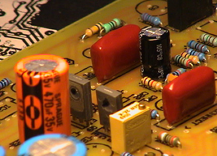 BD139/140 in Modified Board
)
)
)
)
)