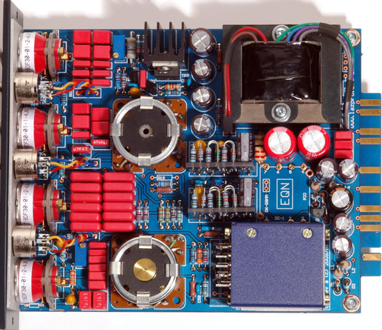
Some notes and observations made while putting together the "Peter Purpose" EQN, a Neve 1084 EQ clone made for a 500 rack. The opinions expressed are my own; use at your own risk.
*Update: see this post for an important fix for this project that may affect your build.
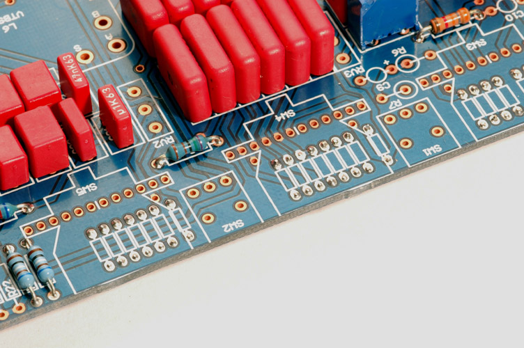
Switch Resistors
For the small resistors that fit on the opposite side of the board I used these:
Grayhill Rotary Switches
Soldering tip for the Grayhill switches: solder the toggle switches on the reverse side of the printed circuit board first. Dry fit the Grayhill rotary switches in their appropriate PCB holes and thread the rotary and the toggle switch bushings through the front panel (not the L shaped piece or you won't be able to solder the bottom of the PCB!). Tighten the rotary switch nuts. Make sure the Grayhill switch PCB pins are fully inserted into the board and tack a single pin on either side of each switch. Check carefully for fit, readjust if required, then solder the remainder of the pins.
One thing I've noticed after using this method - the body of the Grayhills are centered so accurately that the bushings don't touch the L bracket at all. When the EQ is "on" and you adjust either of the top two frequency select switches with metal knobs fitted there is a pronounced increase in hum. The adhesive tape over the switch position select pins apparently insulates the body from the bracket at the rear. The powder coated front panel also effectively insulates the nut from the chassis. Attaching an alligator clip lead to the brass nut at the back of the Grayhill and connecting the other side to ground at the input transformer eliminates the hum but is slightly ungainly. I will try to find a straighforward solution to this and post it here.
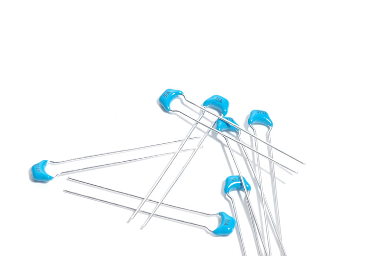
2.5mm Pitch Capacitors
The Murata 2.5mm lead pitch ceramic caps suggested in the build thread are available at Mouser as well as Digikey. Note that as also suggested in the thread an C0G/NP0 cap is not required for the 0.1uF (possibly not required for the others as well, but easy enough to find in the smaller values). Note that the first two listed are X7R, not C0G. These Murata caps have leads that emerge from the body wider than the 2.5mm pitch specified but are factory bent to the listed pitch. It is easy enough to make them fit in places where you need a 5mm pitch as well by re-bending the leads.
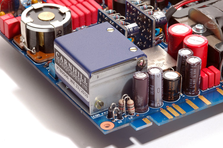
Carnhill Input Transformer
For the input transformer I made a small bracket from some scrap sheet steel:
A bracket is not required as you can just affix the transformer directly to the board using two screws included with the PCB (these apparently need to be cut down as they are a little long). I just liked the idea of securing the transformer with the mounting screws kindly provided in the AML kit (remembering how hard it was to find this unusual screw for an earlier preamp build). If you decide to make a bracket, you can pull the dimensions for the transformer holes from the Carnhill PDF linked from AML's site and the board hole dimensions can be found by simply using the PCB as a template.
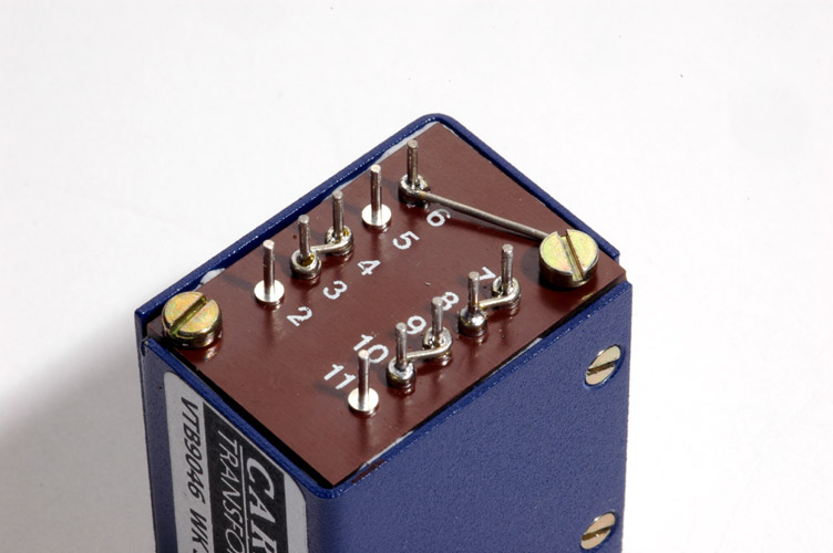
Rather than run wires from each board hole to the input transformer I wired the transformer itself with solid wire first. Input windings in series and output parallel. As the bracket was grounded pin 6 is tied to one of the screws:
This keeps the board wiring minimal rather than the spaghetti mess you would get using individual wires from each PCB pad:
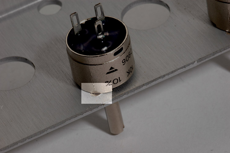
Panel Mount Potentiometers
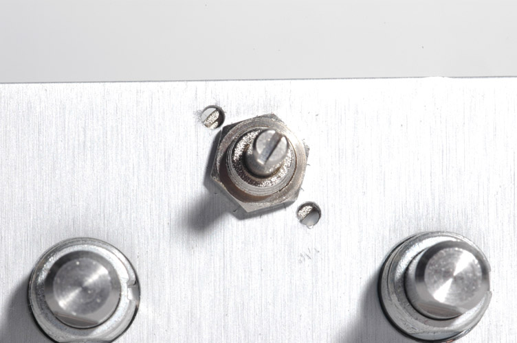
The Vishay PRV6 potentiometers have two small alignment tabs clearly shown in the datasheet. But as supplied, the L-shaped sub-panel only has a single hole making it impossible to mount the pots correctly without doing some drilling:
You cannot use the lock (star) washers supplied with the pots as the milled front panel will not clear the added thickness without modification.
Try to find pots with a long shaft or a knob that is taller than your rotary switch knobs as there is little clearance for your fingers to turn this crucial control otherwise. This is why they are listed as "3X -- TALL KNOBS FOR POTS" in the BOM. In the photo at the top of the page I've used Kilo DDS-50-3-5 (Digi-Key Part Number 226-3037-ND) for the rotary switch knobs that stand 0.625" tall and for the pots I used Kilo HD-50-3-6 (Digi-Key Part Number 226-3015-ND) that are 1" tall for the pots.
500 Rack Additional Parts
Some parts for the 500 (not 51X) build are difficult to find suitable candidates for.
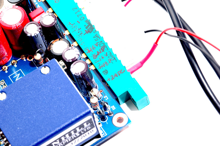
Here are some caps that fit. The first one has the right body diameter but the lead pitch is slightly wide of the PCB drilled holes. They will fit, however. Note that in his photograph it appears that Peter used 470uF/16V capacitors rather than 470uF/25V listed in his BOM. You may find the former 16 Volt part with the correct lead pitch that fits precisely in the board and since the 500 rack supply is well-regulated there shouldn't be a problem using the lower voltage caps. The Nichicon caps I used are shown in the foreground of the picture of the input transformer bracket above.
These Fastron inductors have a suitable current rating and fit well on the board. They are also pictured above next to the tall Nichicon caps:
For the 12 Ohm 2 Watt resistor I used:
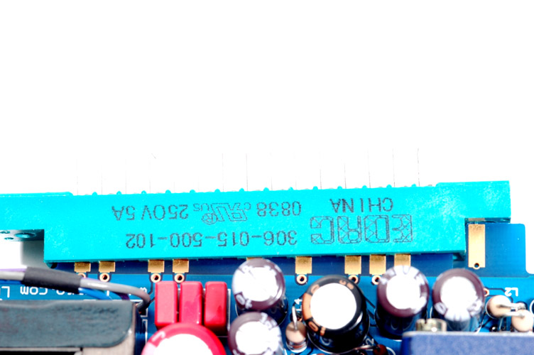
After recently receiving my DC/DC converters from Digikey I noticed some noise that I hadn't heard when using my bench supply straight to the 24V pin. I wanted to use the unit both in my 500 rack and with my 51X jig, so I had a look at the way the EQN board sat in a normal 15 position EDAC connector:
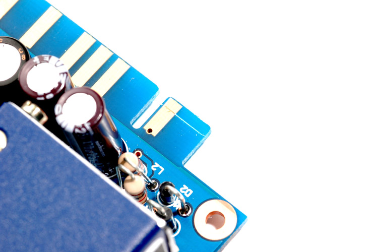
To sit flush, I measured around 2mm that would have to be taken off the 51X tab:
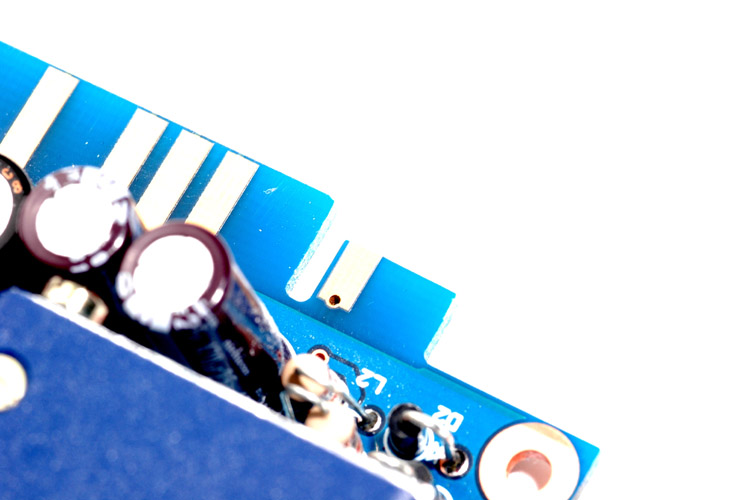
Here it is in a EDAC 15 position connector again from a side view. Fortunately (?) the API Lunchbox itself has no screws holding the EDAC onto the circuit board or this would require further modification of the tab or rack to accomodate the screw head or nut that would protrude from the hole provided:
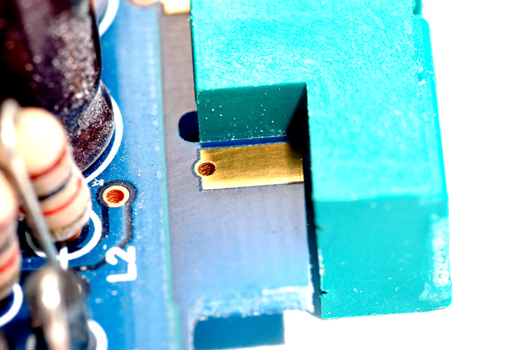
...and in my 51X jig:
Testing continuity on the 24V pin it appears to work just fine.
I terminated the input to the EQN module with a smallish resistor I had lying around and listened again to the output. Even back in the 51X jig the noise was still there.
The noise didn't seem to change much regardless of frequency switch positions. But it did, of course, disappear when the EQ IN switch was switched OUT.
Pulling out the BA284 amps one at a time saw the noise disappear. Having located the offending amplifier board I thought about what might be causing such a popcorn noise. After giving the board a good clean I removed the transistors and found there was one particularly noisy one. Problem solved.
Rather than cross the output transformer primary and secondary leads as many other appear to have done, I mounted the transformer with the leads at the top. While it solves the 'problem' of crossing the leads it does give a kind of Afghan hound look to the wires.
Please do not copy and repost these photographs or link directly to them from my server.
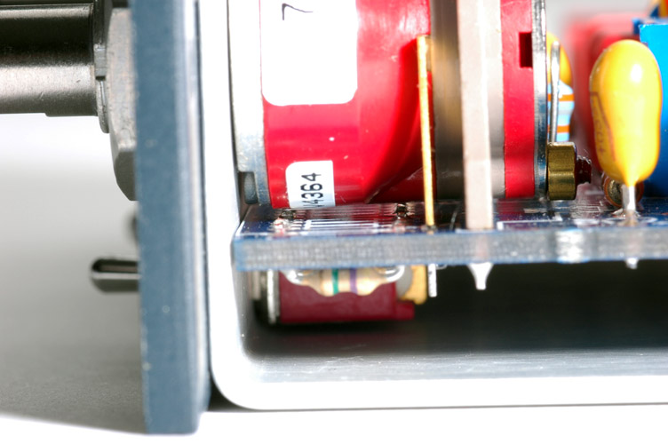
Note that the leads do not have to be cut totally flush with the component side of the board as the Grayhill rotary switches naturally sit slightly proud of the board once installed on the top side. The crucial leads are the ones that sit at the apex of the curvature of the switch body, that is, the ones at the approximate center of the resistor grouping.

*Update: it appears that there was a bad batch of transistors going around as others seem to have had the same problem.