Some notes and observations about building Igor's MixBuzz 500. The opinions expressed are my own; use at your own risk.
This page is not intended to be a step-by-step guide to building the MixBuzz 500, but simply a resource for information about my own build. Additional information and links to other resources can be found in the original build thread. Introduction
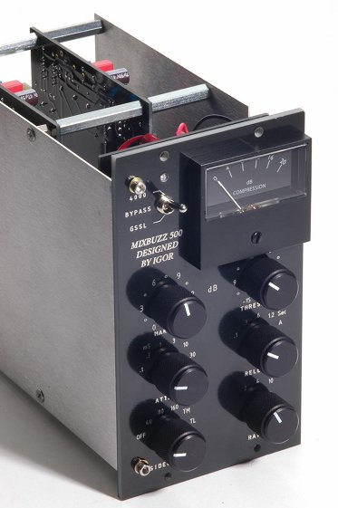
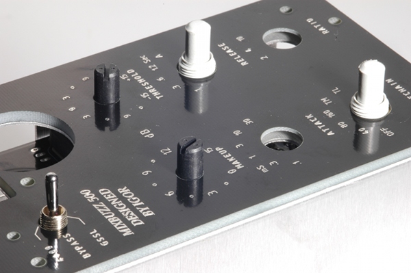
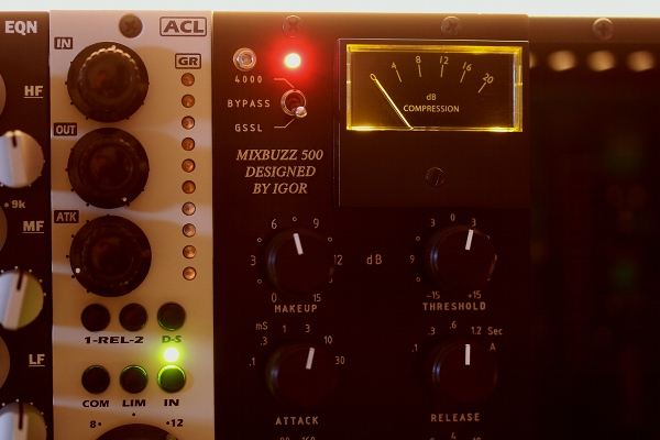
The MixBuzz 500 is a two-space 500 rack interpretation of the SSL bus compressor but with multiple sidechain filters and a "GSSL" mode to duplicate the single VCA detector of the commonly cloned Gyraf version.
Overview
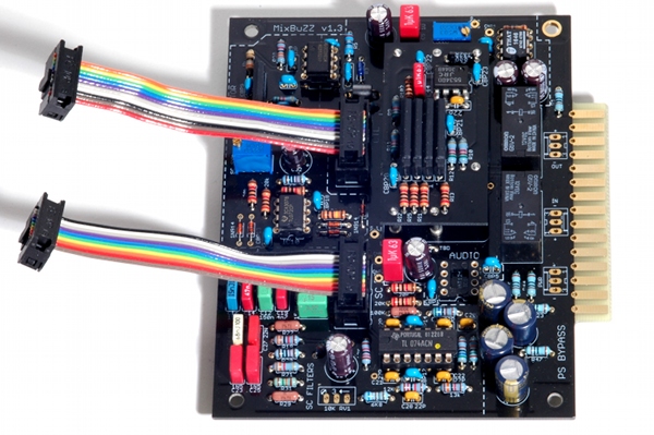
It's important to wrap your head around the way the MixBuzz 500 is assembled so you can have it in mind as you build. Here are some important points to think about:
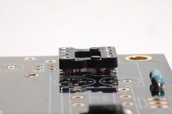
202 Footprint
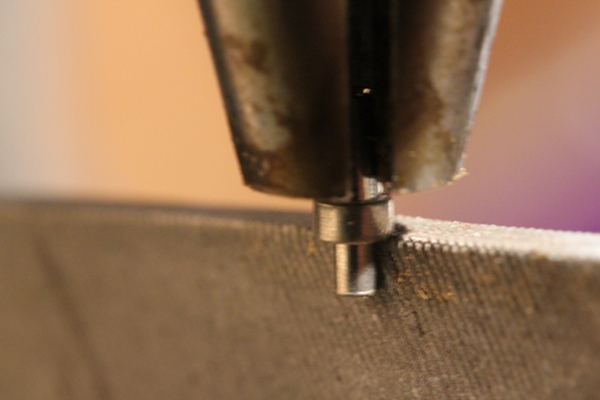
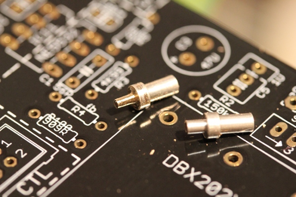
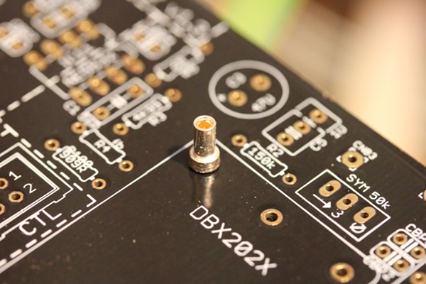
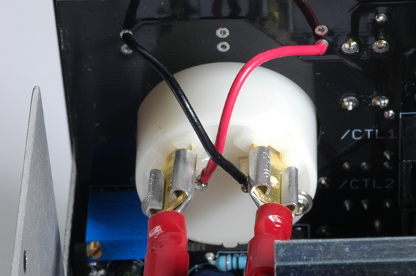
As a DBX "202" VCA footprint had been provided I decided to use sockets so the VCA could be changed easily. But unfortunately the plated through holes on the PCB were far too small to fit the Mill-Max sockets. The double sided board and plated through holes ruled out enlarging the holes by drilling them out.
Instead, I fitted each socket in the Jacob's chuck of a drill press and used a file to reduce the diameter of the solder pin of each socket.
Adding sockets made it easy to pop out the 202X clone assembly included with the MixBuzz kit and put in an old 202 black can for testing. I'm not sure what people see in these old discrete VCAs. The noise alone is appalling. But I'm glad I added this option as my curiousity has been assuaged.
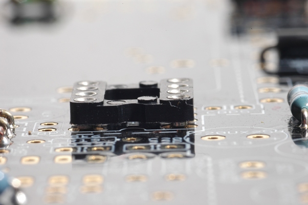
DIP 8 Footprints
I prefer to use Mill-Max turned pin low profile DIP sockets. However, I found that on the MixBuzz 500 audio boards these sockets would only fit two of the four DIP 8 footprints due to the hole sizes being different between the various locations. The Mill-Max sockets have a .038" diameter pin.
Note that the audio input IC socket fits flush with the board while the output IC does not. I ended up using locally purchased higher profile turned pin sockets from Altronics.
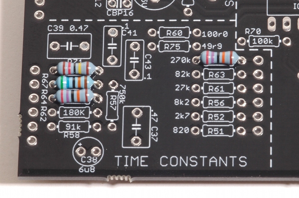
Resistor Footprints
Most of the resistor footprints specified for 1/4 Watt resistors appear to be around 0.3" or 7.6mm pitch, requiring the builder to bend the resistor leads right where they emerge from the body of the resistor. This precludes using one of those handy lead bending gadgets.
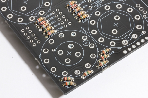
The pitch of many resistors on the control board is even narrower. While 1/4 Watt resistors were also specified here in the official BOM, I used 1/10 Watt resistors, matching the measured values for each pair so the stereo sides would have a better chance of balancing with the resistor's 5% tolerance.
Control Board Shafts
As designed, the two potentiometers on the control board are meant to be soldered flush with the PCB. This means that the pots sit much lower than the Lorlin rotary switches, resulting in the shafts emerging disappointingly shorter than the other control shafts or the toggle switch. Upon testing, the shaft length was too short to mount the Kilo p/n OEDL-63-4-5 knobs I chose to use as the grub screw bit only halfway on toward the end of the shaft.
I ate the $30 USD FedEx charge and ordered another pair of PCW1J-B24-KAB103L Bourns pots.
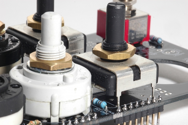
This time I mounted the pots as high as they would go. There is an excess length to both the mounting lugs and the three potentiometer pins themselves and in combination they appear strong enough to hold the assembly securely in place.
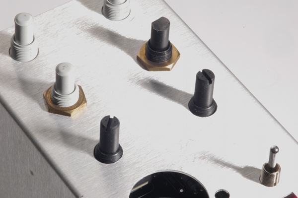
Then I drilled the metal sub-panel of the frame so the threads could protrude through. Similarly, I enlarged the holes of the black front panel with a step bit so the shafts could emerge at their glorious full length.
As the body of the potentiometer does not make contact with the metal sub-panel, I suggest using the brass nut under the panel instead of on top of it like the rest of the Lorlin nuts. If you have some spare nuts you can use them to tighten the pot to the sub-panel from the top but I found that they are secure without another nut.
Meter
The Sifam 19W0-1MA0-100 sells for 150.41 AUD at the Australian element 14 site (formerly Farnell). Great if you're willing to pay the extortionate local price while the Aussie dollar is soaring at record levels. At time of writing the Farnell UK site shows 41.89 GBP; at current rates that is 64.95 AUD.
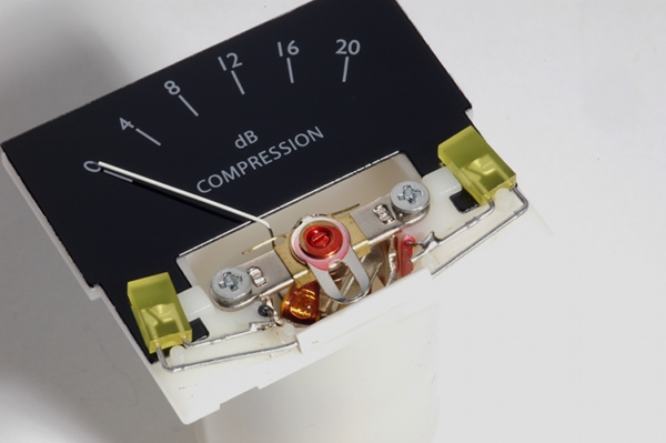
Instead, I opted for the one from Hairball. I wasn't crazy about the bluish-white light from the LEDs that came with the meter, however, so I substituted yellow ones from Lite-On p/n LTL-403Y. These LEDs emit a soft, vintage glow ;^)
Note that the supplied scale is not translucent so backlighting the meter with the LEDs meant to be installed on the control board won't produce the desired effect.
Leave out the three backlight LEDs and instead run wires from the PCB to the light terminals of the Hairball meter. You can retain the 2k value of the series resistor R89 as the total series resistance (R34 + R40 = 20R) of 2.02k gives us 15mA.
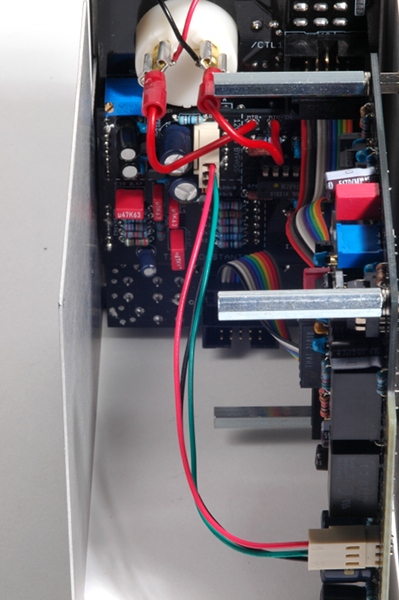
Connectors
Igor's Photobucket pictorial shows the connectors that join the audio boards to the control board in increasing lengths. I found that the following lengths worked well for my build: 8CM, 8.5CM, 9.5CM, 10.5CM.
Each cable assembly is constructed in the same way with all the polarity keys pointed in the same direction as shown. For each audio board there is a control and sidechain connector. Assign a number to each audio board (1,2) and plug each board into the corresponding socket on the front panel assembly - one control and one sidechain for each audio board.
It's the first time I've used these Insulation Displacement Connectors and finally had a use for the multicolored 3M ribbon cable I've had for decades. The plugs are incredibly easy to use - just insert the cable and squeeze the connector in a vise until the top part locks to the body. Each conductor is forced into a V shaped contact creating an electrical connection. How robust this will be over time is uncertain; I've seen similar V shaped contacts on old Neve broadcast consoles that lose continuity over time and are commonly soldered into place upon repair.
For power to the front control assembly, 0.1" pitch connectors can be used. Igor suggests using connectors only on one side; I prefer to use them on both sides as I have some plans that make their use desirable. Note that only one set of wires and connectors is required to provide power to the front board assembly.
Igor also describes soldering the contacts for the 0.1" connectors. As a recent convert to crimped connectors, I recommend purchasing the A crimped connector is a thing of beauty and in contrast to the IDC type contact described above (that has a much smaller area of contact) a crimp is very reliable as the contact area between the wire and pin is large and gas tight. Your car uses hundreds, if not thousands of them. How many times have you needed to repair a crimped connector on your car or found an electrical fault caused by one?
Please do not copy and repost these photographs or link directly to them from my server.
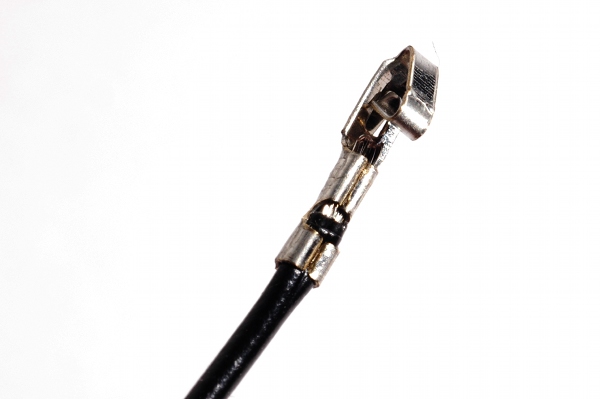
Molex tool #63811-1000 Engineer PA-09. Have a look here for the correct way to perform a crimp. It does take some practice to get it right.