30 September 2017, Modified 1 December 2018
Some notes and observations about the Ampeg PF-50T. The opinions expressed are my own; use at your own risk.
In July 2017 I purchased a used Ampeg PF-50T from a US seller on Ebay. Loud Technology's FAQ about the PF series suggests that they cannot be modified for use in countries where the voltage is different from the point of sale. So for the first few times I used a locally purchased step down transformer to power it up.
I found the level of hum through the speaker - even with the master volume turned down - quite loud. While there were a number of posts about the issue none seemed to present a resolution while many seemed to conclude that the level of hum wasn't objectionable. Perhaps the step down transformer was causing my issue...
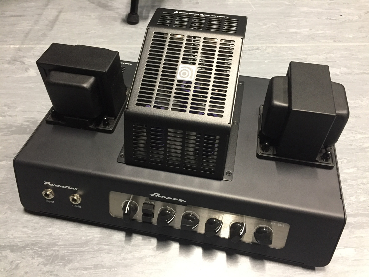
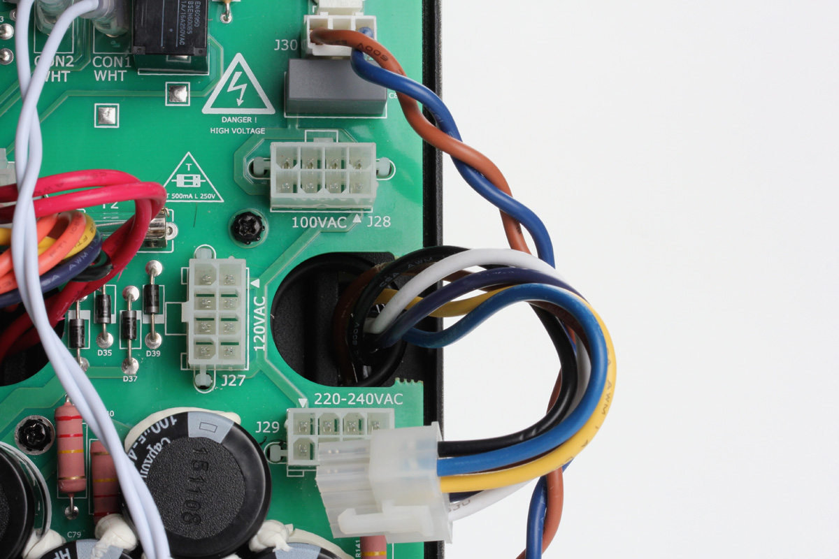
Cracking it open revealed that the PF-50T has a universal primary power transformer that can accommodate both 120 and 240 volt countries as well as Japan (100V).
A Molex-style connector gets moved to the correct socket and the fuse swapped as required. Was it a coincidence that shortly after discovering this fact the same model started selling locally for around 500 dollars less?
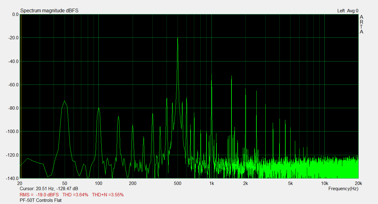
With the newly voltage converted amplifier I began to do some tests and measurements. Here is a spectrum analysis of the "transformer balanced*" line output of the amplifier when fed with a 500 Hz @ 0.135VRMS input signal:
Click for the modified unit under the same conditions.
The result largely agrees with the specifications in the Owner's Manual that quotes an unweighted signal to noise ratio from 20 Hz to 20 kHz of 60 dB.
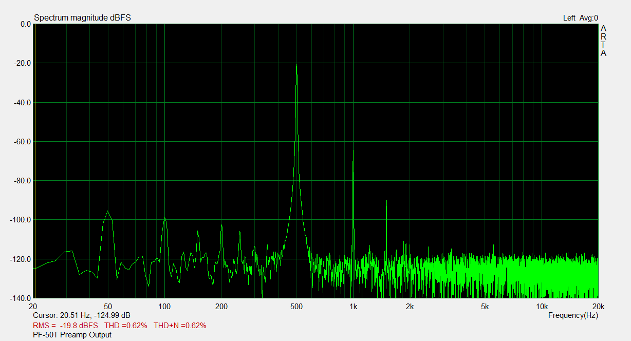
Here's another measurement but without the 500 Hz input signal to show that the residual noise is not just a harmonic of the input signal:
Because the PF-50T has a direct output from the preamp stage post EQ (through the IC buffer/balancer stage) we can measure the noise level from that source alone. The power amplifier is not included in the signal chain. Note that the 50 Hz peak is about 20 dB down from the previous image:
Here is a shot of an oscilloscope trace taken directly from the output transformer secondary with no signal applied:
The noise in a 240 volt 50 Hz environment has a period of 20ms corresponding to 50 Hz. This suggests that filtering of the B+ voltages is not the issue. If it were, the frequency would be 100 Hz due to the full wave bridge.
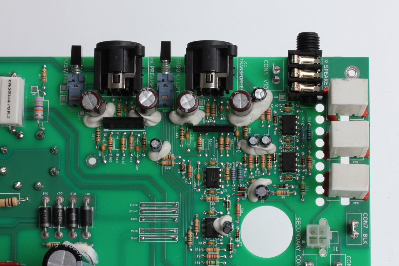
Though I was aware of the previous statement above, it did not stop me from chasing power issues. In doing so I ended up tracing the entire tube audio chain (note that the PF-50T contains seven dual op amp ICs that primarily handle the balanced line outputs). While I was at it I removed and measured the a toroidal inductor in the preamp midrange circuit. Also of interest were the way grounds were handled. Tracing it out proved only that nothing really stood out as an issue.
After a few frustrating weeks poking at it on and off it dawned on me that there was only one half-wave rectifier in the amp. That was the only part of the circuit likely to be the source of line frequency infiltrating the output stage.
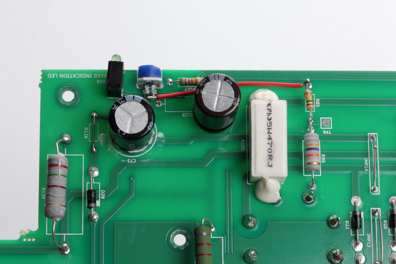
The negative bias circuit differs from other Ampeg and historical circuits from other brands. The 680 ohm resistor increases the charging time constant of the capacitor by decreasing the available current. With the trimmer set to the extreme setting that reduces the voltage to its minimum, there is essentially a 6.8k resistor across the smoothing capacitor that reduces its effectiveness by increasing the load.
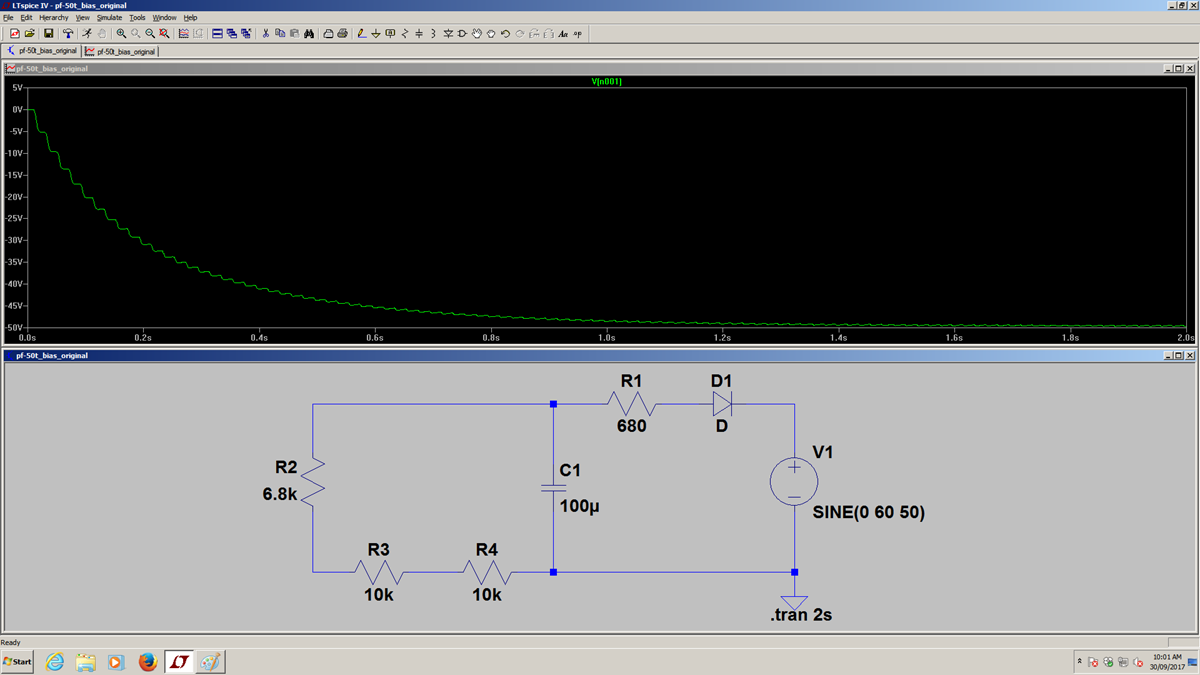
Of course it won't get set to minimum ordinarily. Here's a simulation of the circuit with the bias voltage set to maximum:
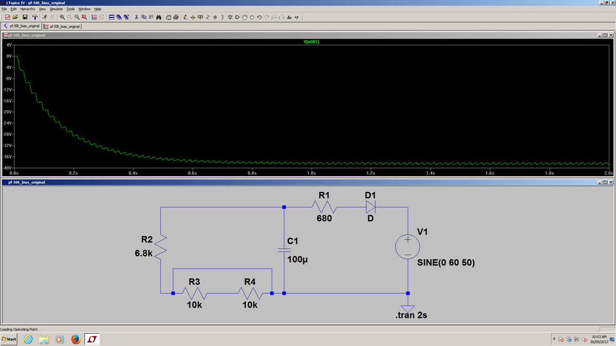
Here is the same circuit with the bias voltage set to minimum:
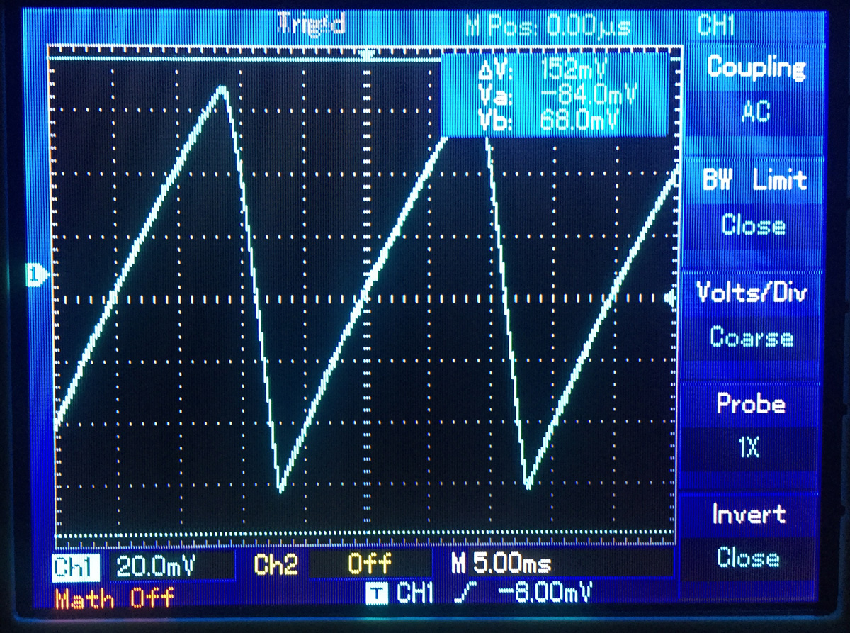
When the PF-50T's bias is adjusted per the Instruction Manual, the measured bias voltage ripple looks like this:
The peak to peak swing is greater that 1.2 volts and correlates with the result of the simulation.
If the circuit is re-arranged like the V-4B reissue the simulation looks like this:
It's better because by moving the resistor there is no longer a limitation on the current going to the capacitor after recitification. Therefore the capacitor charges almost instantaneously. Also, when set to minimum the resistance across the capacitor is 11.5k (6.8k + 4.7k); the moved resistor now forms a divider rather than the crude shunt used in the PF-50T.
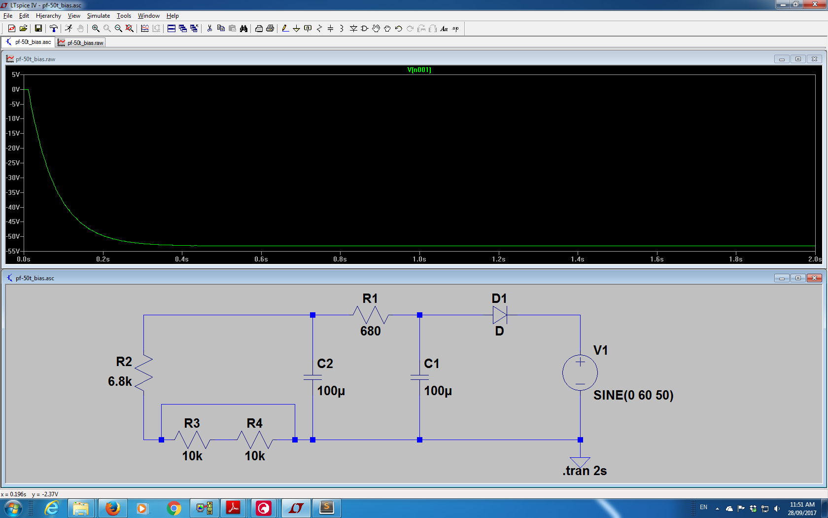
Let's add another like value capacitor and return the resistor to the original PF-50T value. Then we'll adjust the voltage to minimum to put the greatest load on the output:
The only remaining issue is that though the bias is adjusted to minimum with the "pot" shorted out, the voltage is still too high. Now we eyeball the values of our pot simulation, change them from 10k to 1k and rearrange them to the top position. We change the 6.8k resistor to 10k and move it to the spot between ground and the pot. Here are the voltages taken from the bottom, middle and top of the 1k resistor string:
Here is the schematic of the modified negative bias supply. Regardless of the trimmer potentiometer position the 12k resistance that the capacitor sees stays the same. The output voltage can be varied over the same range as the original circuit.
By cutting some traces, drilling a hole and soldering two resistors to the bottom, I managed to add the modifications to the existing PCB:
A Bourns 3306W trimmer potentiometer would probably be ideal but I only had the "K" variant on hand, so the wiper lug had to be bent upward and the red jumper wire attached.
Here is a spectrum analysis of the "transformer balanced" line output of the modified amplifier when fed with a 500 Hz @ 0.135VRMS input signal:
Click for the stock unit under the same conditions.
Notice that the 50 Hz line frequency level is now 20 dB down correlating closely to the Preamp Post EQ Balanced Out. Now the S/N could be quoted as 80 dB, making it much more useful for the average PF-50T player.
If you've managed to read this far I will now tell you a shortcut that will get you about halfway to the performance of the modification described but with far less effort. Simply replace the 100uF/100V capacitor with a 470uF/100V one. Nichicon UHW2A471MHD or United Chemi-Con EKYB101ELL471MK40S have the required 5mm lead pitch to fit the existing footprint of the PCB. The performance will not be as good as the complete modification but it will be a definite improvement over the stock design.
TalkBass member Bertr has devised a simpler modification than my own that requires less disassembly (even less than the simple modification described in the previous paragraph), fewer parts and allows you to use the existing trim pot. Here is a schematic based on his description and confirmed as correct:
Under simulation the usable range is -37.5 to -51.12 volts. He provided a photo of his modification:
Please remember the precautions listed at the top of this page before attempting any of these modifications.
Please do not copy and repost these photographs or link directly to them from my server.
![]()

![]()


