Some notes and observations made while doing a voltage modification of an XLS 1500 power amplifier. The opinions expressed are my own; use at your own risk. Don't attempt this repair unless you are familiar with working on high voltage equipment.
Please do not copy and repost these photographs or link directly to them from my server.
Somehow up until now, in early 2013, the phenomenon of inexpensive Class D PA amplifiers has passed me by unnoticed. It seems like there are more choices now than you can shake a stick at all offering high power and varying degrees of DSP power.
After a little research I decided on the Crown DriveCore XLS 1500. Being the cheapskate that I am I did not want to pay the equivalent of $535.66 US dollars in Australia for something that routinely sells for $399 in the States. I found one on Ebay for the latter price including shipping and jumped, assuming that conversion to 240V would be straightforward.
Despite what you might have read on that font of all knowledge - the Internet - the Chinese-made XLS amplifier's holes in the back do not contain a row of LEDs that show what voltage you have connected your amplifier to. Mine had a white plastic plug showing the configuration that was made at the factory.
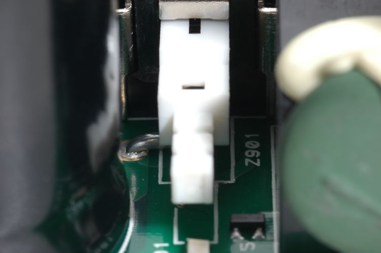
With the main board removed from the chassis I eventually spotted a wire jumper partially hidden underneath the power switch:
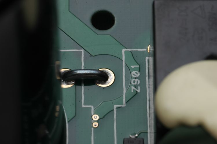
Once the switch was removed the wire and designation Z901 were clear to see. I did a search and turned up this forum post: http://forums.prosoundweb.com/index.php?topic=140553.msg1303348#msg1303348
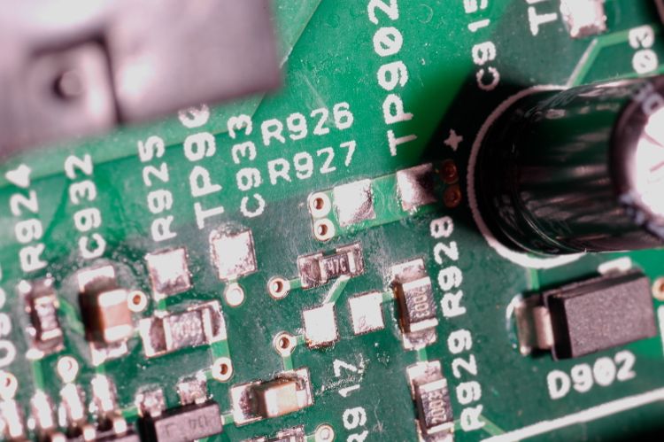
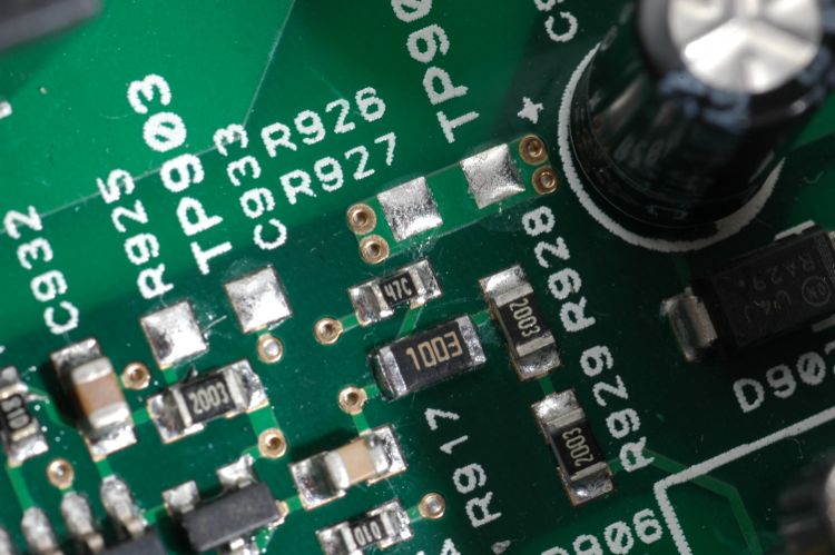
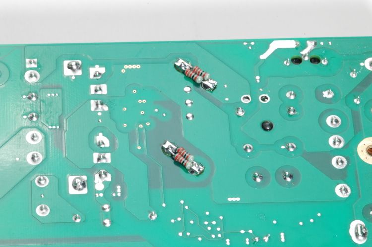
The resistor string composed of R927 to R929 is shown below with R927 already removed. This chain of series-connected resistors comes through the power switch directly from the AC line voltage and feeds a comparator circuit around an LM393 just barely visible in the bottom left of the image below.
The chart for R927 values is a little counter-intuitive. The value indicated for 120V is 121k, not 12.1k as I had mis-read. Then it goes down to 100k for 220V and up to 150k for 240V. I measured the original resistor and confirmed the value is 121k (the graphic attached to the linked post is quite small). I put in a 100k thinking this was closer to the 150k I didn't have but may have to go back and put in the correct value.
After removing the jumper, the AC rectification circuit is now a full-wave bridge rather than the voltage doubler it was with Z901 in place (see the two holes in the upper right quadrant of the picture below). I have to add here that it is a lame idea to simply cut the jumper as some have mentioned. Spend a little time now and do the job correctly or at least clip both ends cleanly flush with the PCB. This will probably require removal of the power switch.
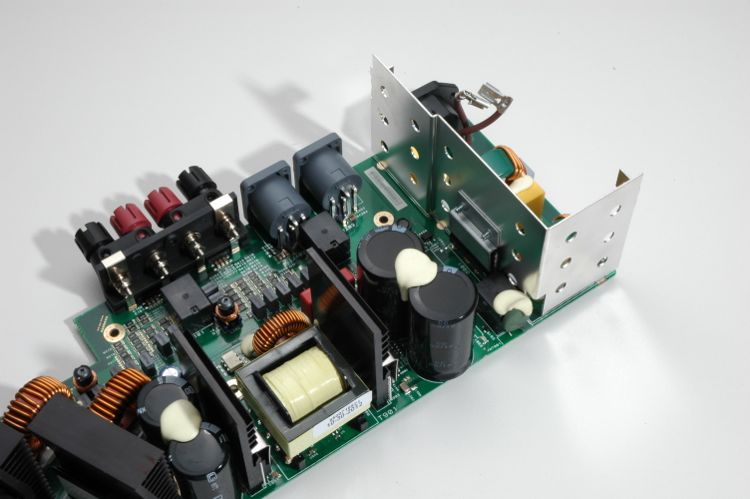
Now the two filter capacitors C911 and C912 are in series with no 1/2 Voltage reference coming from that missing jumper. Apparently the service manual specifies four 82k resistors for R906, R907, R951 and R952. These will form a voltage divider that will hold the common terminals at half the total voltage across the two capacitors so the 200V rating of the caps is never exceeded and each is bearing its fair share of the burden. I could not find two of the four resistor footprints on the board but that hardly mattered since I did not have any surface mount resistors of the correct power rating, let alone value. So I soldered two 0.6W 82k resistors in parallel with each of the capacitors.
The modification shown here allows the previously configured 120V 60Hz model to run directly from a 220V 50Hz line. I have deliberately left out all details about removing the PCB and reassembling the unit to discourage the uninitiated from attempting this modification. A good repair shop should be able to do this modification for about the price difference between the US and AUS model ;^)