The Revision J boards have a feature that had not been documented at all when it was introduced. These boards have the option of changing the ratio of the input and output transformers.
The original formula Gyraf G1176 project used a Lundahl LL 5402 output transformer in a 2:1 step down configuration. When I first developed my alternative board for this project, I decided to incorporate the modification many were doing which was to rewire the transformer as 1:2. I also added a footprint for the OEP A262A2E that many were using at the output as well. This transformer too was wired 1:2.
Sometime later it finally dawned on me that changing the ratio was really just as simple as reversing its orientation on the board. It's hard to believe that I missed something so obvious when I was designing the first prototype. I remember having diagrams scrawled on pieces of paper trying to keep all the pin assignments straight in my head.
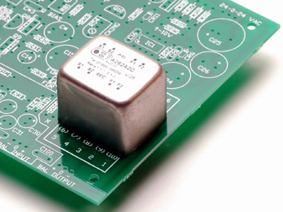
The Lundahl has four pins on one side and five on the other. The center pin on the 'five' side is pin 3, ground. If turned so pin 3 is closest to the Output pads on the board, you get a 1:2 ratio. If you turn it the other way around, you'll get 2:1 as in the original G1176. I'm not certain if Lundahl always puts their label on the top with the same orientation, but the image above shows the 1:2 step-up configuration.
My boards show inside the Lundahl output transformer footprint the legend (2:1OPT). Similarly the pin assignments in parenthesis show the 2:1 option. It's that simple.
In the case of the OEP transfomer, these have two rows of four pins each with a ground pin off to one side of the case. Here it is pictured with the shielding can in the 1:2 configuration. The ground pin is off to the left side.
Funnily enough, I have put a 1:2 legend on the PCB where the ground pin goes for the OEP 1:2 configuration. On the opposite side of the OEP footprint is another legend that says 2:1. If you drop the ground pin for the OEP there, guess what? You'll get a 2:1 step-down output configuration.
Lundahl Input Options
As originally conceived by Jakob, the Lundahl input transformer option is configured as a 1:1 ratio circuit. PRR pointed out in his post that a step-down configuration is preferable in this circuit. This is easy to accomplish with my latest revision boards.
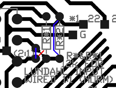
Find the area just to the right of the transformer like the above image. Cut the trace marked in red on the reverse side of the PCB. It is easy to find as it runs diagonally and is thinner than the other tracks. Now run wire links between the pads as marked in blue. The two resistors marked R*1 and R*2 are not installed in the 2:1 configuration.
Next, install the Lundahl LL1540 input transformer as usual. It will now operate as a 2:1 stepdown transformer.
OEP Input Options
Similarly, the OEP transformer is configured for a 1:1 ratio if dropped in per the silkscreen legend on the top of the board. But by following the instructions on the bottom side - cutting two traces and soldering a wire link where shown - the OEP can be inserted "backward", giving a 2:1 stepdown configuration.
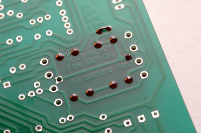
By inserting the ground (case) pin in the hole marked "2:1 GROUND PIN" the orientation of the transformer is flipped for the 2:1 input ratio.
)
)
)
)