Please note that the following instructions are for the pushbutton version only, using my pushbutton layouts posted on the main 1176 page. While there are some similarities between wiring the pushbutton version and the rotary, there are as many differences too. I'll document both in time.
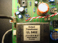
 Going through the schematic we move on to the output pot. Note that the pad assignments here do not correspond to the input pot pads. The shield connects to the pad closest to the board edge. The middle pad will eventually connect to the opposite lug from the shield. The last pad goes to the wiper (middle lug), so I've assigned it the orange wire as I did with the input pot. Try to keep the ends of the wire which are exposed from the shield as short as possible. I'm sure you can do a better job than I did in this respect.
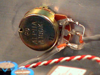 The opposite end of the cable you just soldered to the board gets hooked up to the pot just like in the previous example for the input pot. Once you've done that, you need to strip another piece of shielded cable. A single conductor cable will do, although in my example I've just used another piece of two conductor and connected the two conductors together. Note that I have tried to minimize the exposed central conductors by shortening them once I've stripped back the insulator and twisted the shield together. I've used two pieces of heat shrink here - one over the long shield lead and another over the junction where the foil is just barely exposed where the outside sheath covers the conductors. I suggest you do the same to prevent shorts from occuring if the wire is somehow bent or twisted. Connect the shield of this new wire to the same lug the previous shield was connected to. The central conductor on this length of cable goes to the opposite lug.
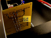
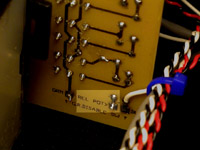
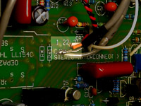
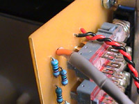 Strip back the insulation on the other end of this wire. Remove the foil and shield to expose the central conductors to about 1/4" or around 5mm. You will not be connecting this end of the cable to ground. Put a bit of shrink tubing around the end of the cable to keep whatever is left exposed of the foil or shield from being able to short against any other wiring. Strip back and solder the central conductor(s) to pad 15 (connects to R26, 56k) of the ratio board as pictured.
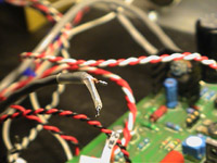
 From here we're going to deviate from the flow of the schematic and address those black and red wires in the photo above. Those are just normal stranded hookup wire that I've twisted for appearance sake. The black wire is soldered to pad 20 and the red wire is soldered to pad 21 of the ratio board. No particular reason for the assignment other than to be able to trace the wires easily on the other side...
No surprises here - the other ends of the black and red wires go to pads 20 and 21 respectively on the main board.
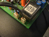
 Back to the signal flow of the audio through the schematic. Solder a twisted pair of stranded wire to the X and Y pads of the main circuit board.
These wires will carry the output signal to the meter board so that you can switch in the VU meter to monitor the output. They do carry an audio signal but are not susceptible to hum so shielded wire isn't required here.
 Solder the other end of the twisted pair of wires to pads X and Y on the pushbutton meter board. In the original version, there is both a +4 and +8 metering switch but in my pushbutton and the Gyraf rotary version the +8 position has been eliminated. The +4 switch sets the VU meter to monitor the audio output of the limiter.
It isn't crucial that you get X and Y to their respective pads on the meter board, but try to for sake of thoroughness and general accuracy.
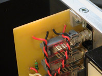
 Now wire the output header paying close attention to polarity. In the Gyraf Rev 7, the polarity is the opposite of my boards. If you've wired the header incorrectly though, it is a simple matter of switching the crimp plugs by freeing them from the housing and rearranging them.
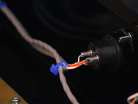 Wire the other end of the output cable to the output jack. Shield is terminal 1, positive is terminal 2 and negative is terminal 3. This completes the audio wiring of the unit, but there's still plenty to do.
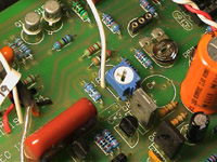
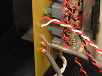
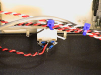
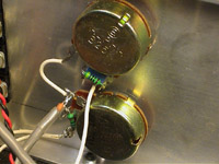 There's a lot to take in here so take a deep breath. These are the attack and release potentiometers from top to bottom respectively. Unlike the rotary switch versions, the pushbutton boards do not contain the components associated directly with the attack and release pots. These are instead wired directly onto the pots.
R76, the 470 ohm resistor and C22, the .022uF capacitor (the blue object slightly obscured by the resistor and potentiometer body) are wired in parallel and soldered to the 25k attack pot lugs as shown at the counter-clockwise and wiper (middle) position. The counter-clockwise (CCW) position of the potentiometer is determined by the lug at which the wiper comes to rest when the shaft of the potentiometer is turned to the extreme counter-clockwise position when viewed from the front. If measured with a multimeter with the shaft in the CCW position, the two lugs which show close to zero ohms are the two in which the components are soldered.
Similarly R79, the 270k resistor is soldered directly to the CCW and wiper lugs of the 5M release pot.
Next, a short piece of wire gets soldered between the attack and release pots between the two clockwise lugs (the short white wire in the image above). From this junction solder the center conductor from a piece of shielded wire whose shield has been stripped back and heat shrinked like in the previous example (pad 15 of the ratio board) to insure that the shield on this side does not accidentally touch any part of the circuit.
 The other end of this wire will go to pad 7 on the main board and to the ground terminal. Cut this cable to the proper length and prepare it as shown. Note that the center conductor(s) is cut short while the shield is cut long and covered with a piece of heat shrink tubing.
This is to ensure adequate shielding while still making connections with the proper pads on the main board. This particular part of the circuit is crucial as the impedance is high and susceptible to interference from outside sources. While you wouldn't necessarily hear this interference directly, it could cause your limiter to misbehave and possibly decrease the maximum achievable compression ratio.
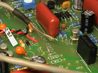 Now solder the center conductor(s) to pad 7 of the main board. Also, note that this IS the same wire pictured above, I just replaced the clear heatshrink with black between photos. On my boards there is a pad marked G just above the legend STEREO in the image. Solder a thick, short bare wire to this pad such as the excess off one of the 1N400x diodes that you used in the power supply and line amplifier circuits.
You'll be soldering another shield to this point so just leave it there for the moment. If you are using the Gyraf Rev 7 board you will have to find another ground point on the board, drill an additional hole in a blank part of the board near the point pictured and solder a bare wire to it.
Referring again to the image of the attack and release pots above, solder a plain stranded hookup wire to the CCW lug of the attack pot. This is the white wire coming off the bottom lug of the top pot near the resistor/capacitor.
 Cut this wire to length and solder it to pad 19 which, somewhat confusingly, comes after pad 21. This pad feeds the DC output of the control amplifier to the attack and release controls.
Refer again to the attack and release pot image. There are TWO white wires soldered to the bottom lug of the release pot on the CCW (resistor) end. One of these wires goes to the ratio board and one goes to pad 18 on the main board. Solder the two wires to the potentiometer lug and cut them to length.
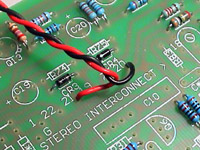
 One length of wire goes to the REL POT terminal on the ratio board. This pad connects to one of the two R87s in the schematic, the ratio board 150 ohm resistor.
There is another R87 on the main board in the power supply section. Please DO NOT connect this wire to the main board or you will certainly have problems!
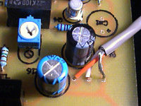
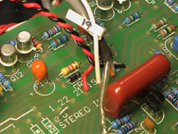
 The other wire you are left with is soldered to pad 18 on the main board, near trim pot R81. If you are using my boards, please ensure that you have used the correct pad for the style of trimmer you used.
There are two pads and only one should be connected to the wiper of your trim pot. If I had used the style of trimmer pictured to the right of the blue one (R54) in the R81 position I would have used the hole above the legend 18 in the image.
 Strip back the shield on another piece of wire and do the heatshrink thing. Solder it to pad 22 on the meter board. This wire is for the Gain Reduction Disable switch.
The original UREI 1176 has the GR Disable attached to the attack pot. It's very hard to find a potentiometer with a SPDT switch these days, so here we've relocated it to the position where the seldom-used +8 meter switch used to go.
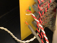
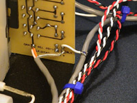
 Run this shielded cable past the ratio board. Where it passes by the board, strip back a band of insulation to expose the shield inside. Take some plain stranded hook-up wire, strip about an inch of insulation off one end and wind this around the exposed shield. Solder it in place taking care not to melt the insulation of the conductors inside.
Take the other end of the hook-up wire and solder it to the BLK pad on the ratio board.
 Solder the other end of the shielded cable to pad 22 on the main board. Attach the shield to the one left unsoldered previously from pad 7 and solder both shields together to the short piece of wire you soldered to the ground pad.
 Straddling pad 22 on the meter board are two pads labelled "BLK" and "GRN" (designations are from the original UREI schematic). Prepare a piece of shielded cable with a long shield wire and short center conductors. Cut a piece of heat shrink for the shield.
Solder the shield to pad BLK and the center conductors to the pad labelled GRN.
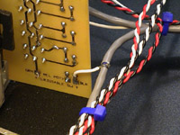
 Prepare the other end of the shielded cable as you did the first end and solder it to the ratio board pads marked BLK and GRN.
Because the switch boards don't face each other but rather the copper side of the ratio board faces the top of the meter board, it is probably easier just to solder onto the back side of the board as I've done in the image.
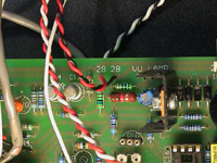
 Next, look at the picture on the right. The twisted pair on the left are soldered to pads 28 and 29 of the meter board. Might as well solder another twisted pair to the pads on the right marked VU.
 Take the twisted pair you soldered to the meter board pads 28 and 29 then solder them to the respective pads on the main board located near the voltage regulator.
 Solder the other pair of twisted wires from the meter board to the VU meter terminals. Don't wire them to the VU meter lamp terminals!
You'll note in the picture that I've had to make a little germanium diode bridge to convert the cheap, fake "VU" meter into something that will function somewhat similar to a real VU. If you bought a real VU meter the bridge will be internal and you'll just connect the wires directly to the terminals. Some VU meters have screw terminals with nuts that tighten to make the connection. Put two crimp eyes on the wires to use this type of terminal.
The only thing left to connect is the VU lamp. Please consider that at the main board VU lamp terminals there is a 35 volt potential so unless your VU lamp runs at 35 volts you should not consider connecting the lamp directly to these terminals.
I will try to add more material about hooking up the VU lamp soon.
If you power up your clone now you should be able to run through the calibration procedures. Congratulations on wiring up your 1176!

)
)
)
)
)
)
)
)
)
)
)
)
)
)
)
)
)
)
)
)
)
)